Clamping device

a technology of clamping device and clamping plate, which is applied in the direction of positioning apparatus, metal-working machine components, manufacturing tools, etc., can solve the problems of affecting the switching operation, and reducing the durability of the clamping devi

Inactive Publication Date: 2006-01-24
PASCAL ENG
View PDF7 Cites 21 Cited by
  • Summary
  • Abstract
  • Description
  • Claims
  • Application Information

AI Technical Summary

Benefits of technology

[0015]In the hydraulic cylinder, there is provided an annular hydraulic chamber formed by the cylinder bore formed in the clamp body, a piston member for driving the pull rod downward, and a collet supporting member. In the cylindrical hydraulic chamber, the piston member is provided with a greater pressure receiving area than the pressure receiving area of the collet supporting member. Therefore, greater hydraulic pressure is applied to the piston member than to the collet supporting member. Thus, with the collet being biased upwardly, the piston member is pushed down and the tapered rod portion is moved downward. Then, the tapered rod portion forces the collet to elastically deform in a diametrically expanding manner and, simultaneously, slightly move downward so that the workpiece is drawn and locked to the workpiece receiving surface in a reliable manner.
[0017]a) The collet supporting member has a top end wall at the top end, the upper half of the piston member is slidably fitted in the collet supporting member, and the top end of the piston member abuts against the bottom of the top end wall when hydraulic pressure in the annular hydraulic chamber is released to unlock the workpiece. The piston member is biased upward by a bias means for unlocking the clamp, such as a spring. The top end of the piston abuts against the bottom of the top end wall when hydraulic pressure in the annular hydraulic chamber is released to unlock the workpiece. The bias force is applied to the collet member by the bias means via the collet supporting member. Therefore, the collet member is also biased upwardly. Hence, there is no need of providing another bias means for preventing the collet member from coming down when the workpiece is unlocked.

Problems solved by technology

Inevitably, the clamping device has reduced durability.
However, it would be difficult to say that high durability is obtained thereby.
Hence, the hydraulic system must be switched each time a workpiece is locked and unlocked, complicating the switching operation.

Method used


Image

  • Clamping device
  • Clamping device
  • Clamping device

Examples


Embodiment Construction

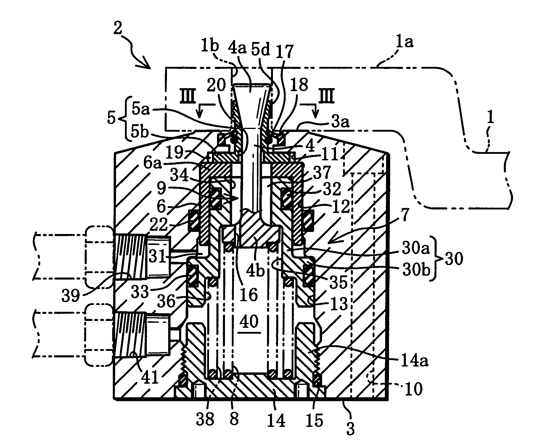
[0026]An embodiment of the present invention is described hereafter, with reference to the drawings. In this embodiment, the present invention is applied to a clamping device for locking a workpiece to machine it.

[0027]As shown in FIG. 1, a workpiece 1 to be machined has a flange 1a, through which a vertical bore 1b having a relatively small diameter (for example 6 mm) is formed for locking the workpiece 1.

[0028]For example, in order to machine the top surface of the flange 1a of the workpiece 1, plural clamping devices 2 are provided for locking the workpiece by utilizing vertical bores 1b formed through the flange 1a, on a work fixing base such as workpiece pallet (not shown).

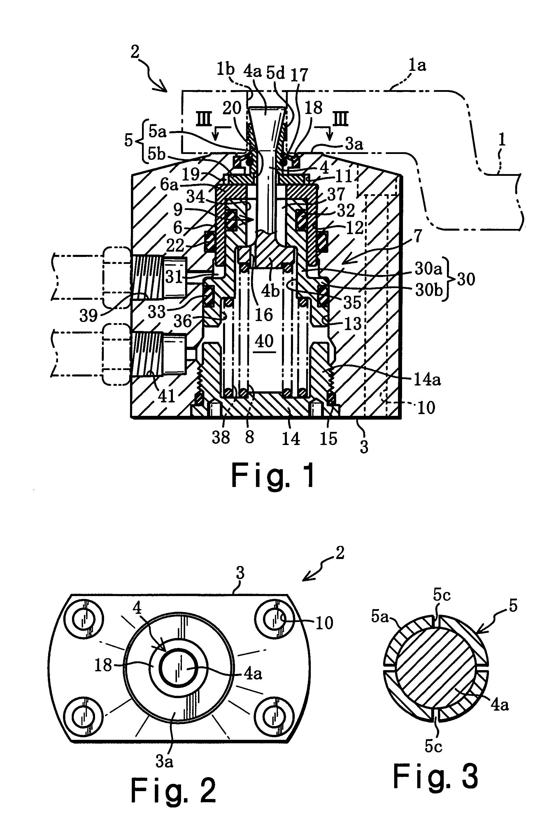
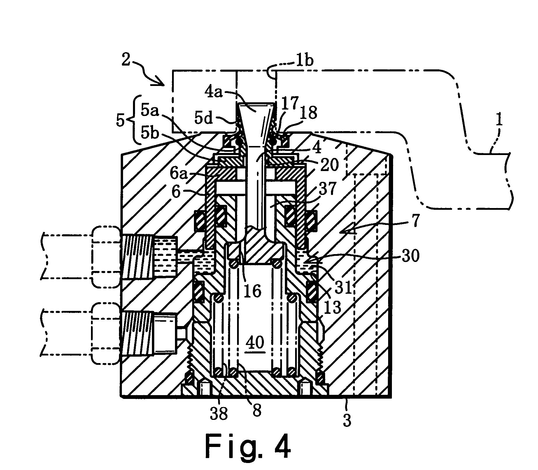
[0029]As shown in FIGS. 1, 2, 4, an output portion of the clamping device 2 is detachably engaged in the vertical bore 1b of the workpiece 1 to lock the workpiece 1.

[0030]The clamping device 2 comprises a clamp body 3, a pull rod 4 mounted in the clamp body 3 in a manner in which it is vertically movable and ...


PUM

PropertyMeasurementUnit
diameteraaaaaaaaaa
pressureaaaaaaaaaa
distanceaaaaaaaaaa

Abstract

A clamping device 2 is provided with a hydraulic cylinder 7 for biasing a collet member 5 upward via a collet supporting member 6 and driving a pull rod 4 downward. A piston member 30 has a greater pressure receiving area than the collet supporting member 6 in the circular hydraulic chamber 31 of the hydraulic cylinder 7. Therefore, the hydraulic cylinder 7 can drive the pull rod 4 downward while the collet member 5 is biased upward. Meanwhile, the collet 5a of the collet member 5 is resiliently deformed in a diametrically expanding manner to engage in the vertical bore 1b of a workpiece 1 while slightly moving downward, ensuring a secure locking of the workpiece 1 to a workpiece receiving surface 3a.

Description

TECHNICAL FIELD[0001]The present invention relates to a clamping device for clamping a workpiece by using a bore formed therein, and particularly relates to a clamping device in which a pull rod is retracted so that a collet fitted on the pull rod is elastically deformed in a diametrically expanding manner to lock the workpiece.BACKGROUND OF THE INVENTION[0002]Conventionally, a variety of clamping devices for locking a workpiece to be machined on a workpiece fixing table such as a workpiece pallet, have been proposed or are in practical use.[0003]Among these, a clamping device for drawing and locking a workpiece to the table is described, for example, in Laid Open German Patent Publication DE-4020981-A1. As shown in FIG. 5, the clamping device 100 described in this publication has a clamping body 101 in which a pull rod 102 is provided to be vertically movable and protrudes upwardly. The pull rod 102 is provided at the top end with a tapered rod portion 102a having a tapered shape t...

Claims


Application Information

Patent Timeline
Patent Type & Authority Patents(United States)
IPC IPC(8): B23B3/00B23Q11/00B23B31/40B23Q1/00B23Q3/00B23Q3/06
CPCB23Q1/009B23B31/402
Inventor KAWAKAMI, TAKAYUKI
Owner PASCAL ENG
Why Eureka
Try Eureka