Rivet, riveted joint structure riveting apparatus, and riveting method
- Summary
- Abstract
- Description
- Claims
- Application Information
AI Technical Summary
Benefits of technology
Problems solved by technology
Method used
Image
Examples
Example
[0053]A first embodiment of the first and second aspects of the present invention will be explained with reference to FIGS. 6A to 6C and 7.
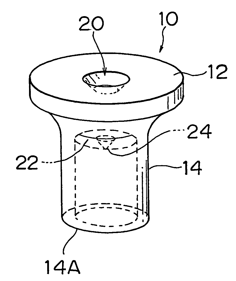
[0054]As shown in FIG. 7, a rivet 10 of the present embodiment is a hollow rivet that consists of a head portion 12, and a cylindrical portion 14 extending from the back surface of the head 12. The head portion 12 of the rivet 10 is formed at its substantially central portion with a recess 20 having an inverted, truncated conical shape. Also, a projection 24 having a conical shape is formed on a bottom 22 A of the cylindrical portion 14 of the rivet 10.
[0055]A riveting or fastening method using the rivet of the present embodiment will be now explained. Initially, as shown in FIG. 6A, a distal end 14A of the cylindrical portion 14 of the rivet 10 is positioned on one (16) of two plates 16 and 18 to be fastened.
[0056]Next, as shown in FIG. 6B, the head portion 12 of the rivet 10 is pressed or driven by a first punch 32 so that a die 34 disposed on ...
Example
[0062]Next, a second embodiment of the first and second aspects of the present invention will be described with reference to FIGS. 9A to 9C. In these figures, the same reference numerals as used in FIGS. 6A to 6C showing the first embodiment are used for identifying corresponding elements, of which no detailed description will be provided.
[0063]In the present embodiment as shown in FIG. 9C, the bottom wall 20B of the recess 20 of the head portion 12 of the rivet 10 is punched out.
[0064]Next, the riveting method of the present embodiment will be explained. Initially, as shown in FIG. 9A, the distal end 14A of the cylindrical portion 14 of the rivet 10 is positioned on one (16) of two plates 16, 18 to be fastened.
[0065]Next, as shown in FIG. 9B, the head portion 12 of the rivet 10 is pressed or driven by a first punch 32 so that a die 34 disposed on the side of the plate 18 causes the distal end portion 14A of the cylindrical portion 14 of the rivet 10 to deform radially outwards.
[006...
Example
[0071]Next, a riveted joint structure according to the third embodiment of the present invention will be explained with reference to FIGS. 11A, 11B and 12.
[0072]As shown in FIG. 11A, a rivet of the present embodiment is a self-piercing tube-like rivet. A rivet body 50 as a whole assumes a cylindrical or tubular shape.
[0073]As shown in FIG. 11B, axially opposite ends 50A and 50B of the rivet body 50 have flat surfaces perpendicular to the direction in which the rivet is driven into a workpiece (direction of arrow A in FIG. 11B). In an axially middle portion of the rivet body 50, a plastic deformation restricting portion 50C is formed over the entire thickness of the rivet body 50 (in the direction of arrow B in FIG. 11B). More specifically, the rivet body 50 is made of a metal, such as iron, that may be subjected to heat treatment, and the plastic deformation restricting portion 50C is formed by heat treatment, such as thermal quenching or high frequency quenching, so as to be less l...
PUM
Property | Measurement | Unit |
---|---|---|
Length | aaaaa | aaaaa |
Angle | aaaaa | aaaaa |
Deformation enthalpy | aaaaa | aaaaa |
Abstract
Description
Claims
Application Information
- R&D Engineer
- R&D Manager
- IP Professional
- Industry Leading Data Capabilities
- Powerful AI technology
- Patent DNA Extraction
Browse by: Latest US Patents, China's latest patents, Technical Efficacy Thesaurus, Application Domain, Technology Topic.
© 2024 PatSnap. All rights reserved.Legal|Privacy policy|Modern Slavery Act Transparency Statement|Sitemap