
Mandibular repositioning assembly

a mandibular and assembly technology, applied in the field of mandibular repositioning devices, can solve the problems of long treatment time, unsatisfactory headgear, and embarrassment, and achieve the effect of reducing possibility, reliably and effectively

Inactive Publication Date: 2006-01-24
3M INNOVATIVE PROPERTIES CO
View PDF38 Cites 29 Cited by
  • Summary
  • Abstract
  • Description
  • Claims
  • Application Information

AI Technical Summary

Benefits of technology

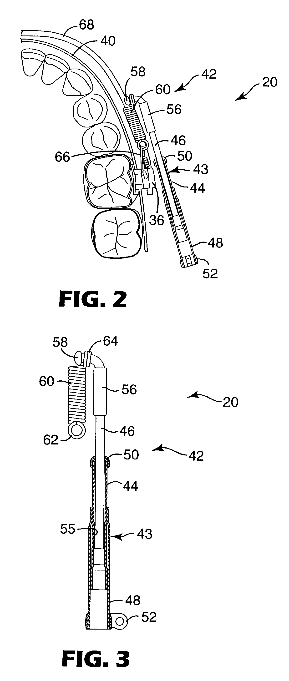
[0025]The present invention is directed to an orthodontic device that connects the upper and lower jaws, and urges the lower jaw to posture toward a position of proper occlusion or Class I relationship when the jaws are closed. The device includes a telescoping assembly having a force limiting spring at one end, and the spring has a central axis that extends in a direction generally along the dental arch. The spring is connected to a molar appliance and serves as a force limiting means. The device functions reliably and effectively for the duration of treatment, and the spring reduces the possibility that the device or other components will fracture or detach from the patient's teeth.
[0029]In certain embodiments of the invention, an adjustable coupling interconnects the coil spring and the attachment. The coupling enables the correction force applied by the brace to be applied in stages, thereby reducing the possibility of imposing trauma to the patient.
[0030]Preferably, the telescoping assembly includes a third member that is slidable relative to the first member. The provision of three members helps to reduce the probability that the members might detaching from one another as the jaws are fully opened.

Problems solved by technology

However, headgear is often considered unsatisfactory because it is visibly apparent.
Headgear may serve as a source of embarrassment, particularly among child and teenage patients who may experience teasing from classmates.
The embarrassment can be somewhat reduced if the orthodontist instructs the patient to wear the headgear only at night, but unfortunately such practice may lengthen treatment time since the desired corrective forces are applied during only a portion of each calendar day.
However, these modules are typically removable by the patient for replacement when necessary, since the module may break or the elastomeric material may degrade during use to such an extent that the amount of tension exerted is not sufficient.
Unfortunately, orthodontic devices such as headgear and removable force modules are not entirely satisfactory for use with some patients, because the effectiveness of the devices is dependent upon the patient's cooperation.
Neglect of the patient to faithfully wear the headgear each day or install new elastomeric force modules as appropriate can seriously retard the progress of treatment and defeat timely achievement of the goals of an otherwise well-planned treatment program, resulting in an additional expenditure of time for both the patient and the orthodontist.
However, the biasing force provided by the spring tends to move the dental arches relative to each other over a period of time.
However, some of the devices known in the past for repositioning the dental arches are considered to present problems when a hard stop is provided as the jaws are closed.
Specifically, if the jaws tend to posture to a Class II relationship during jaw closure, the resulting forces on various appliances in the oral cavity can be significant.
This force may fracture the device or other components connected to the device, or cause attachments such as brackets and buccal tubes to be detached from the teeth.
There is also the possibility that the broken components may contact and injure the oral tissue and cause significant pain.
However, such modifications are not considered entirely satisfactory due to the increased bulk and expense of the replacement components.
However, the resistance to tensile forces of elastomeric modules may deteriorate over a period of time.
In addition, the force limiting or shock-absorbing effect provided by the elastomeric modules is dependent on the freedom of the auxiliary archwire to slide in the auxiliary passages of the buccal tubes, and such sliding freedom may be hindered by the difficulty of sliding a curved section of the auxiliary archwire within a buccal tube passage that has a straight configuration.

Method used


Image

  • Mandibular repositioning assembly
  • Mandibular repositioning assembly
  • Mandibular repositioning assembly

Examples


Embodiment Construction

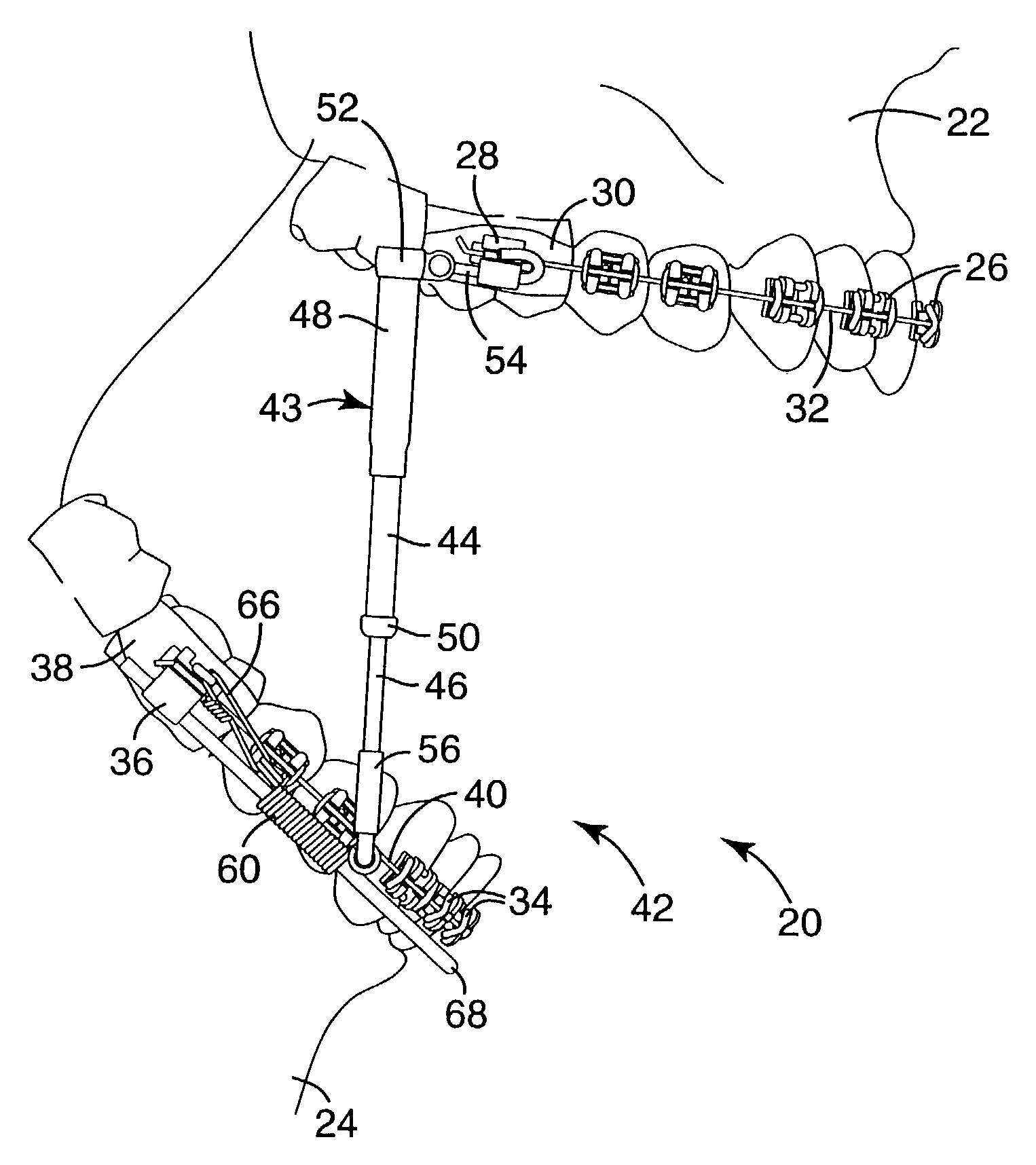
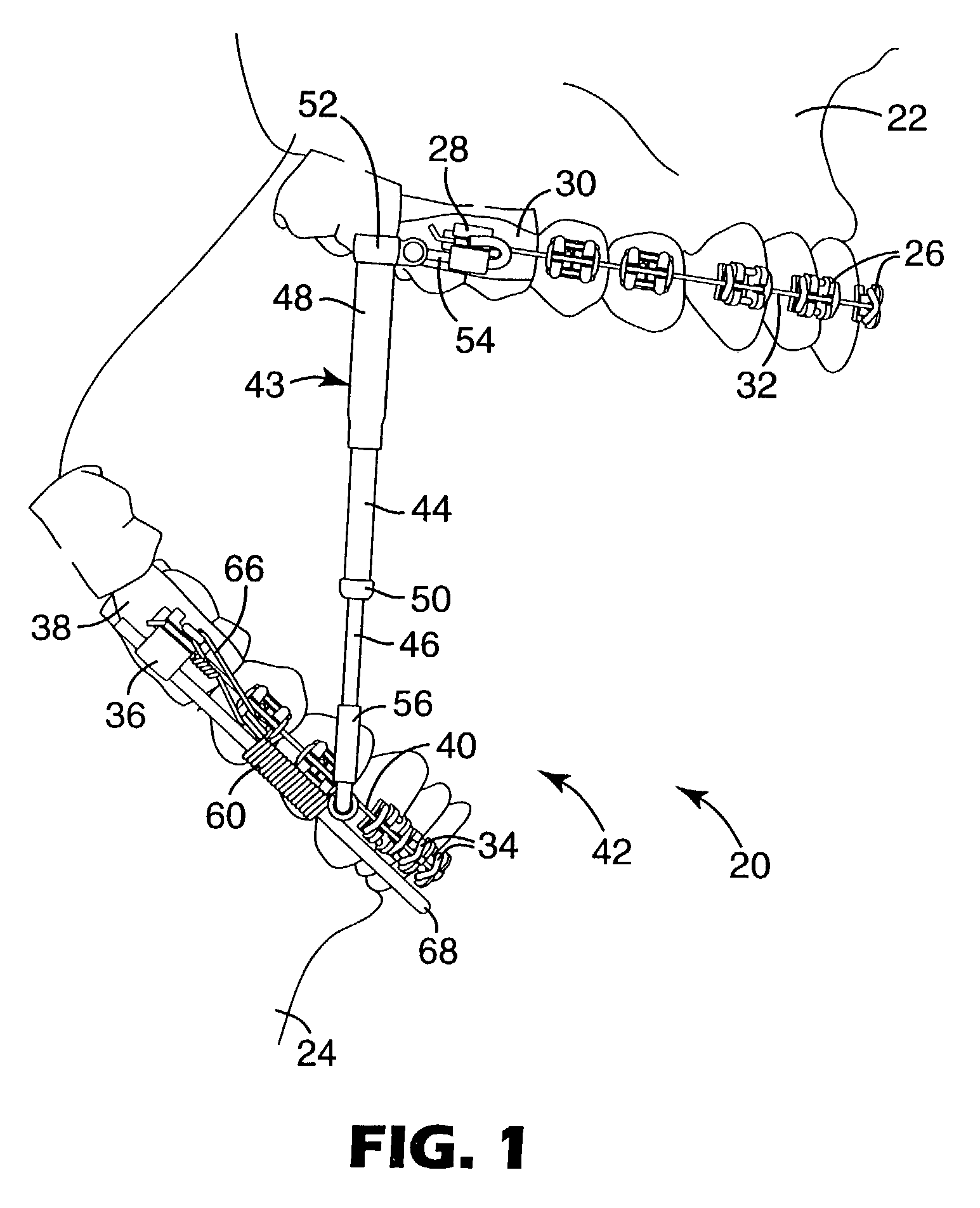
[0037]FIG. 1 is an exemplary illustration of a patient undergoing orthodontic treatment. An orthodontic brace, generally designated by the numeral 20, is connected to the upper or maxillary jaw 22 of the patient as well as to the lower or mandibular jaw 24 of the patient. The jaws 22, 24 are shown in their fully open position in FIG. 1.

[0038]The brace 20 includes a series of upper appliances or brackets 26 that are connected to anterior, cuspid and bicuspid teeth of the upper jaw 22. The brace 20 also includes a molar appliance such as a buccal tube 28 that is connected to the upper right first molar tooth. In this example, the buccal tube 28 is fixed to an orthodontic band 30 that encircles the first molar tooth. An upper archwire 32 extends through slots of the upper brackets 26 as well as through a passage in the buccal tube 28.

[0039]The brace 20 further includes a series of lower appliances or brackets 34 that are fixedly connected to the anterior, cuspid and bicuspid teeth of t...


PUM


Abstract

A device for correcting the relative position of the jaws of an orthodontic patient includes a telescoping assembly along with a coil spring. As the patient's jaws are closed, the telescoping assembly exerts a force against the spring which tends to posture the jaws in correct occlusal relationship. The coil spring provides a yieldable force that avoids the need for a rigid, hard stop as the patient's jaws are closed.

Description

BACKGROUND OF THE INVENTION[0001]1. Field of the Invention[0002]This invention relates to a device useful during orthodontic treatment for repositioning the mandibular jaw. More specifically, this invention relates to a mandibular repositioning device for urging the lower jaw in a forward direction relative to the upper jaw in order to improve occlusion.[0003]2. Description of the Related Art[0004]Orthodontic treatment involves movement of malpositioned teeth to orthodontically correct positions. During treatment, tiny orthodontic appliances known as brackets are often connected to anterior, cuspid and bicuspid teeth, and an archwire is placed in a slot of each bracket. The archwire forms a track to guide movement of the brackets and the associated teeth to desired positions for correct occlusion. Typically, the ends of the archwire are held by appliances known as buccal tubes that are secured to the patient's molar teeth. The brackets, archwires and buccal tubes are commonly referr...

Claims


Application Information

Patent Timeline
IPC IPC(8): A61C7/00A61C7/36
CPCA61C7/36
Inventor CLEARY, JAMES D.
Owner 3M INNOVATIVE PROPERTIES CO
Learn More