Spine stabilization system

a stabilization system and spine technology, applied in the field of soft stabilization systems, can solve the problems increasing the degeneration of the spine, and further injury to other components of the spine, and achieves the effect of increasing the rigidity of the flexible element and increasing the rigidity

Inactive Publication Date: 2006-01-24
GLOBUS MEDICAL INC
View PDF94 Cites 669 Cited by
  • Summary
  • Abstract
  • Description
  • Claims
  • Application Information

AI Technical Summary

Benefits of technology

[0013]Another embodiment of the invention is directed towards a novel prosthesis for intervertebral or intersegmental stabilization designed to ensure proper alignment and motion between vertebrae of the spinal column that helps partially unload the discs and facet joints to give pain relief.
[0017]One embodiment of the invention limits rotation of a first end of a flexible element relative to a second end to a range of from about 10 to about 30°, while in another embodiment the range is limited from about 1° to about 6°. In yet another embodiment, rotation is limited to a range of from about 0° to about 3°. In another embodiment, the flexible element prevents rotation of the first end relative to the second end.
[0021]Locking mechanisms may be used in any of the embodiments of the invention. Thus, in one embodiment of the invention a locking mechanism may secure one or more flexible elements in a rigid configuration. One benefit of this feature, for example, is that the surgeon may have flexibility of the system when positioning the components to avoid bony anatomy, but then be able to make the system more rigid once the component is in its desired position or configuration. In one embodiment, the locking mechanism comprises a cable disposed within a flexible element. The cable can be tensioned to secure one or more flexible elements in a rigid configuration. In another embodiment, the locking mechanism comprises a cable disposed outside of said a flexible element, and as the cable is tensioned it secures one or more flexible elements in a rigid configuration.
[0022]In one embodiment of the invention, a solid rod is disposed within the tubular structure of a flexible element to increase the stiffness of the flexible element.

Problems solved by technology

Components of a motion segment that move out of position or become damaged can lead to serious pain and may lead to further injury to other components of the spine.
Underlying causes of structural changes in the motion segment unit leading to instability include trauma, degeneration, aging, disease, surgery, and the like.
There are several disadvantages to fusion, however.
In addition to a loss of mobility, fusion also causes the mobility of the motion segment to be transferred to other motion segments of the spine.
The added stresses transferred to motion segments neighboring or nearby the fused segment can cause or accelerate degeneration of those segments.
One other disadvantage to fusion is that it is an irreversible procedure.
In addition, it is believed that fusion of a motion segment has a clinical success of approximately 70 percent, and often does not alleviate pain experienced by the patient.
Thus, while such fusion systems have been used since the early 1960's, the intentionally rigid designs have often caused stress concentrations and have directly and indirectly contributed to the degeneration of the joints above and below the fusion site (as well as at the fusion site itself).
Finally, removal of portions of the motion segment unit reduces the amount of support available for the affected motion segment unit.

Method used


Image

  • Spine stabilization system
  • Spine stabilization system
  • Spine stabilization system

Examples


Embodiment Construction

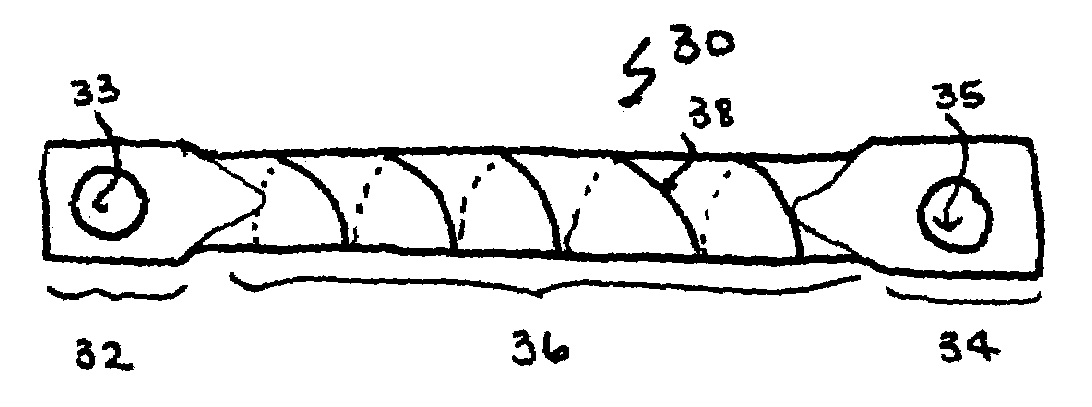
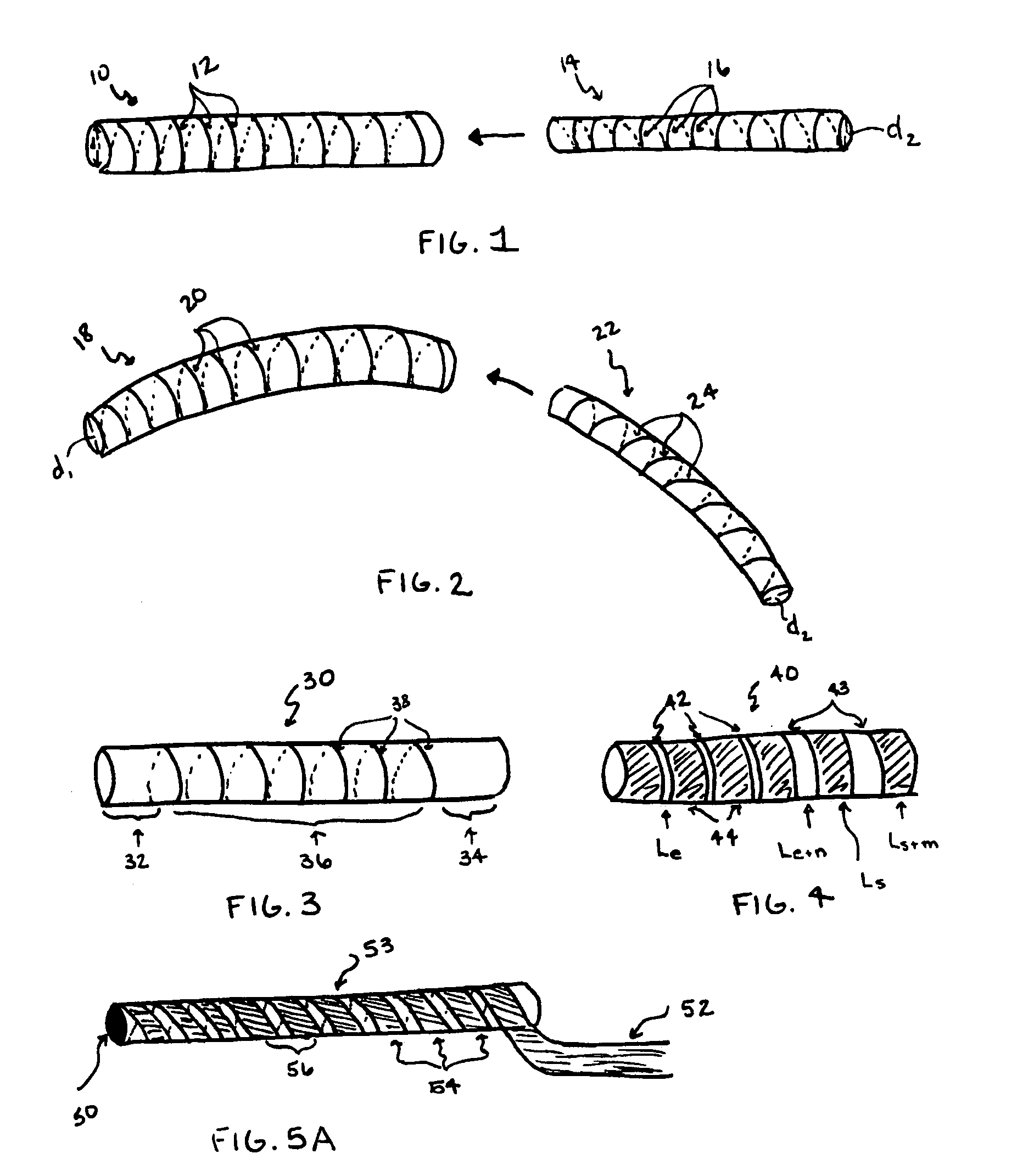
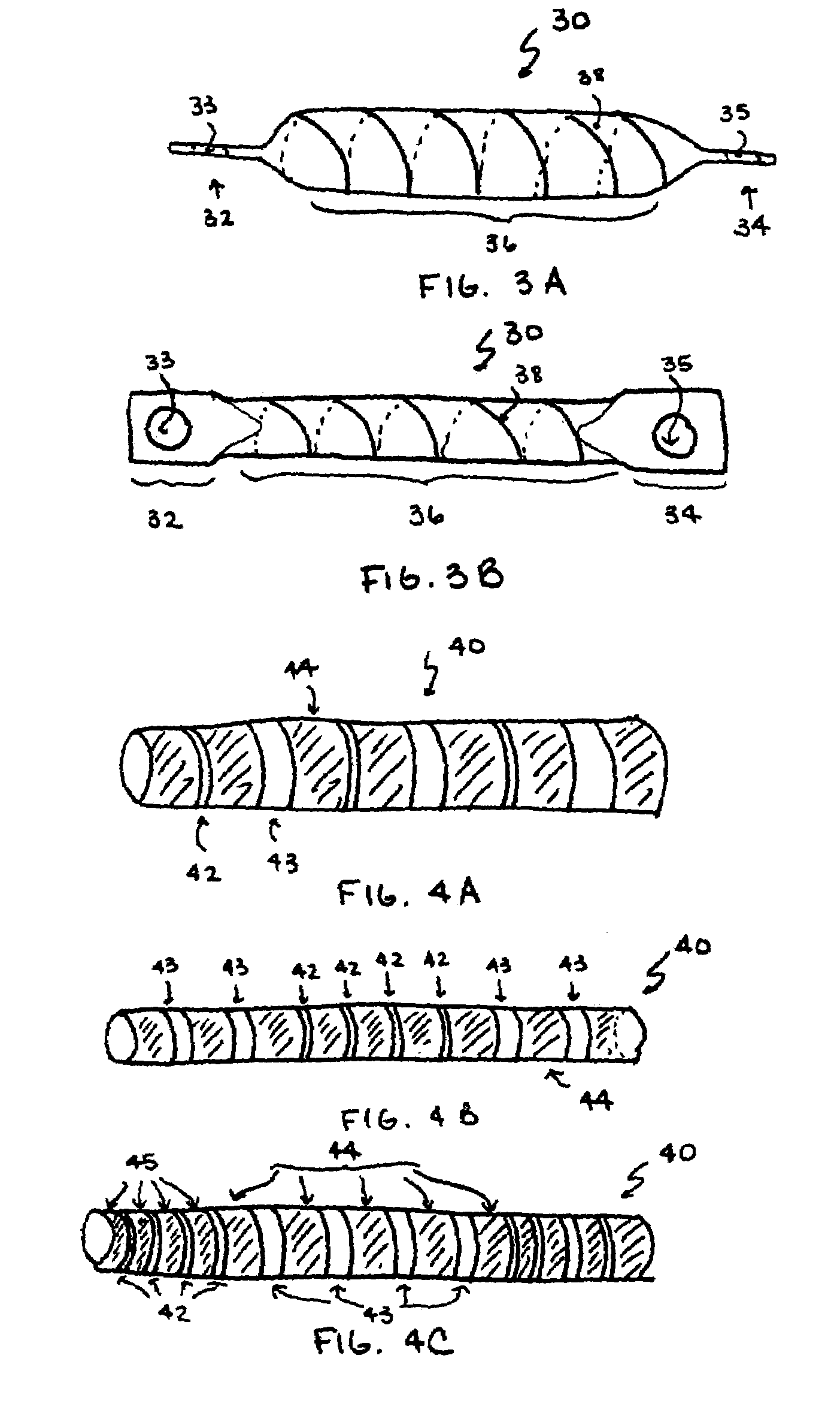
[0058]The present invention is directed to flexible stabilization systems for use with the anterior, antero-lateral, lateral, and / or posterior portions of at least one motion segment unit of the spine. The systems of the invention are designed to be conformable to the spinal anatomy, so as to be less intrusive to surrounding tissue and vasculature than existing solid stabilization systems.

[0059]The system of the invention is contemplated to be used on the cervical, thoracic, lumbar, and / or sacral segments of the spine. For example, the size and mass increase of the vertebrae in the spine from the cervical to the lumbar portions is directly related to an increased capacity for supporting larger loads. This increase in load bearing capacity, however, is paralleled by a decrease in flexibility and an increase in susceptibility to strain. When rigid immobilization systems are used in the lumbar segment, the flexibility is decreased even further beyond the natural motion restriction of t...


PUM


Abstract

The invention generally concerns a spine stabilization system having one or more flexible elements having an opening or slit. The flexible element may be integrally formed in a rod having ends capable of receiving fasteners. The flexible element may limit rotation, flexion-extension, or lateral bending of the spine. The slit or opening may form helical pattern on the rod, and more than one slit or opening may be provided. The flexible element may be conformable to the natural spinal movement.

Description

CROSS REFERENCE TO RELATED APPLICATIONS[0001]This application is a continuation in part of U.S. application Ser. No. 10 / 443,755, filed on May 23, 2003, the entirety of which is incorporated herein by reference thereto.FIELD OF THE INVENTION[0002]The present invention relates to soft stabilization systems for spinal motion segment units. In particular, the present invention is directed to a soft stabilization system including at least two bone fasteners and a flexible central portion conformable to the natural spinal movement.BACKGROUND OF THE INVENTION[0003]The spine includes a series of joints routinely called motion segment units, which is the smallest component of the spine that exhibits kinematic behavior characteristic of the entire spine. The motion segment unit is capable of flexion, extension, lateral bending and translation. The components of each motion segment unit include two adjacent vertebrae and their apophyseal joints, the intervertebral disc, and the connecting liga...

Claims


Application Information

Patent Timeline
Patent Type & Authority Patents(United States)
IPC IPC(8): A61B17/56A61B17/00A61B17/70A61B17/80
CPCA61B17/7023A61B17/7025A61B17/7028A61B17/7029A61B17/8085A61B17/7026A61B17/7004A61B17/7007A61B17/701A61B17/7011A61B2017/00526A61B17/7037A61B17/7049
Inventor PAUL, DAVID C.LEE, ANDREW
Owner GLOBUS MEDICAL INC
Why Eureka
Try Eureka