Pool skimmer

Inactive Publication Date: 2006-01-24
GREATHEAD JAMES
View PDF12 Cites 13 Cited by
  • Summary
  • Abstract
  • Description
  • Claims
  • Application Information

AI Technical Summary

Benefits of technology

[0017]The object of the present invention is to make the cleaning of the top surface of any type o

Problems solved by technology

One of the difficulties in maintaining a pool is to make sure that any fallen debris including leaves, twigs, and moss is trapped as soon as possible.
Otherwise, this material wi

Method used


Image

  • Pool skimmer
  • Pool skimmer
  • Pool skimmer

Examples


Example

[0026]It is the object of this invention to trap and collect debris on the top surface of a pool on a continuous basis without the necessity of an individual operating a net or other skimming device. It is designed to be portable and lightweight to enable the pool owner to position this device where the greatest need is present.

[0027]The principal advantages of continuous skimming of the debris from the top surface of the pool include the reduced maintenance that may become necessary as a result of the failure to clean the surface and to insure that the skimmers, which are built into the side of the in ground pool work at maximum efficiency. If the skimmers become clogged the pool filter will operate at reduced efficiency. This will lead to maintenance problems for the pool owner. It is the further object of this invention to assist the skimmers operate at maximum efficiency by reducing the amount of floating debris.

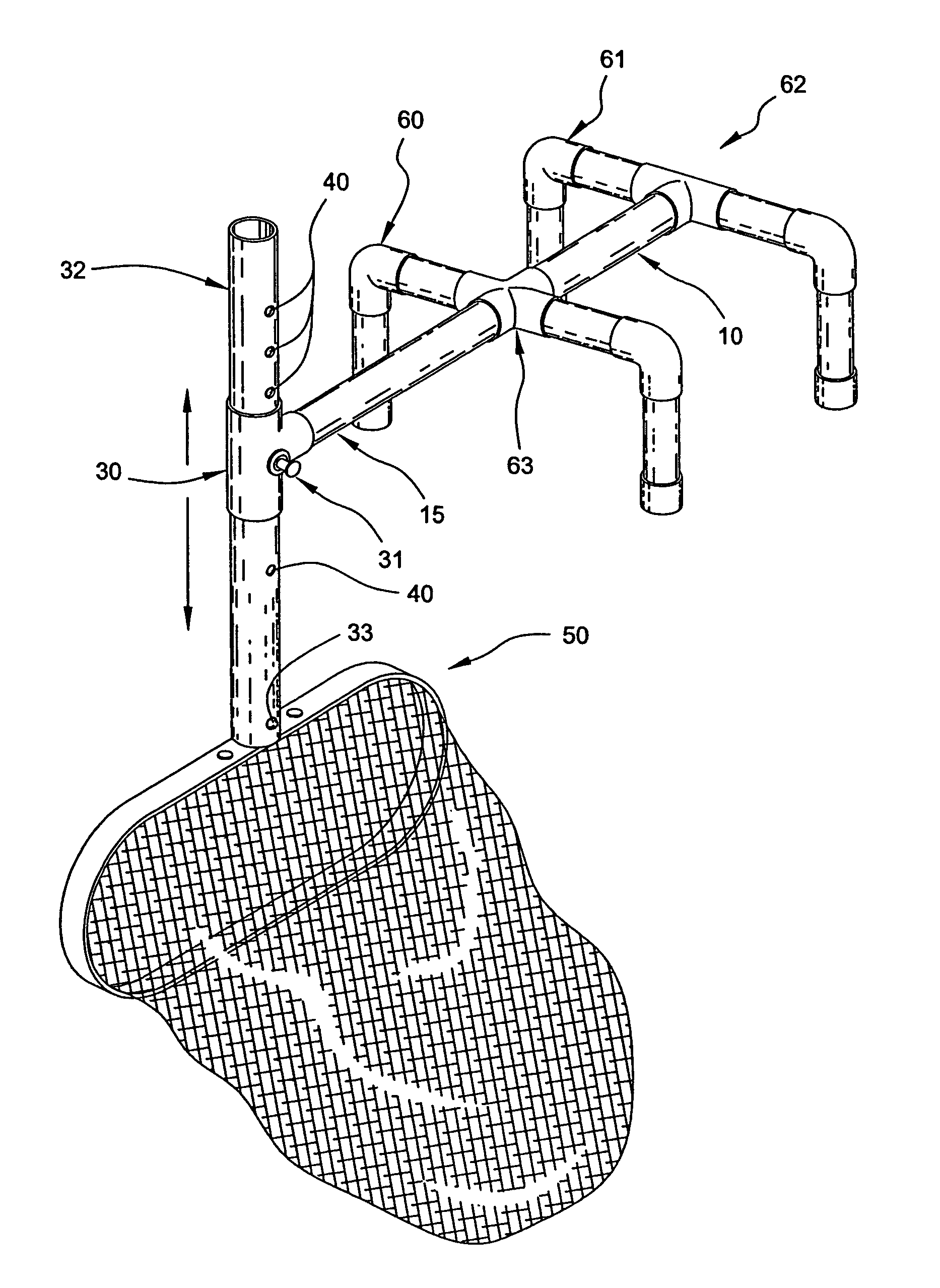
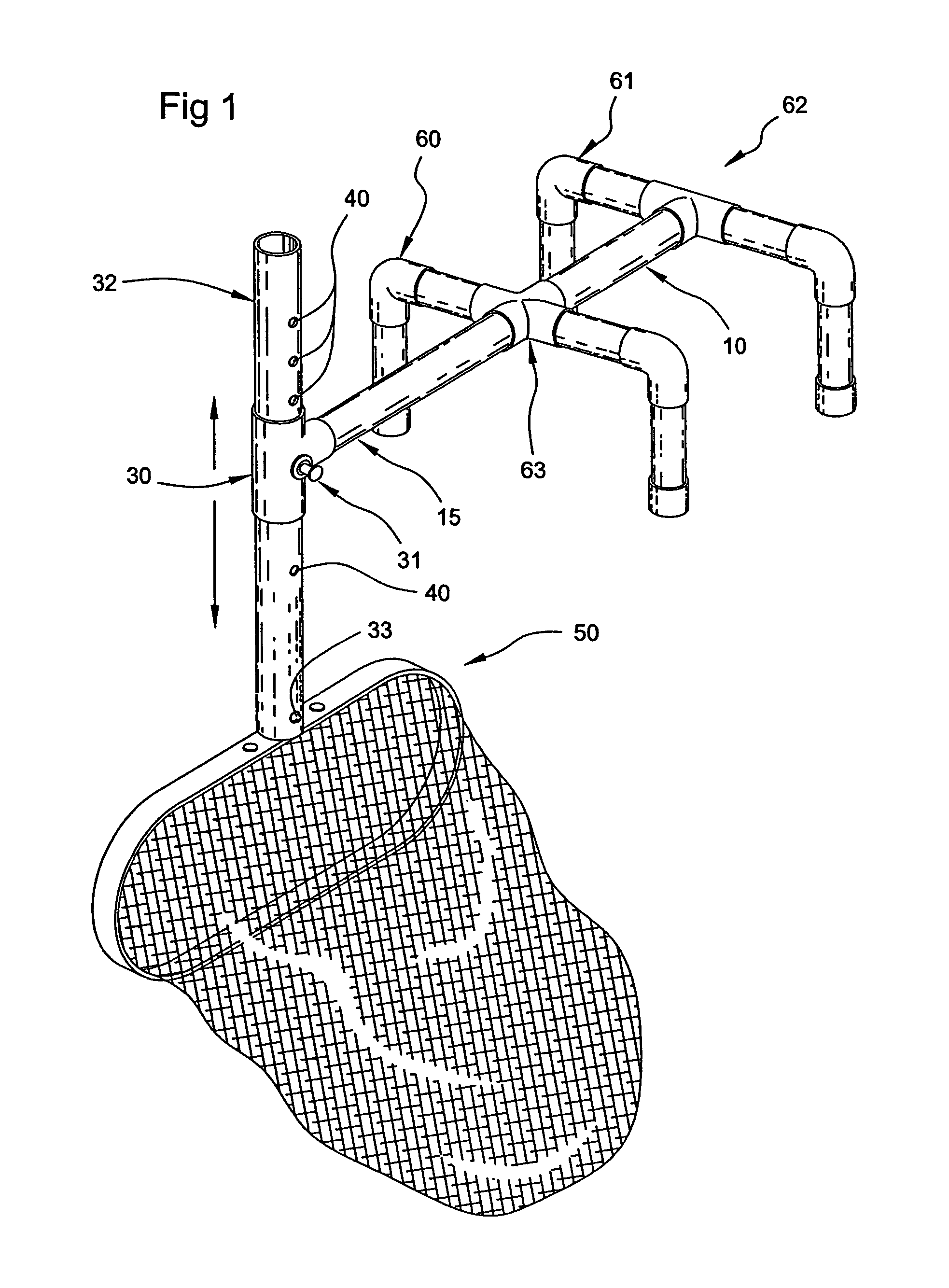
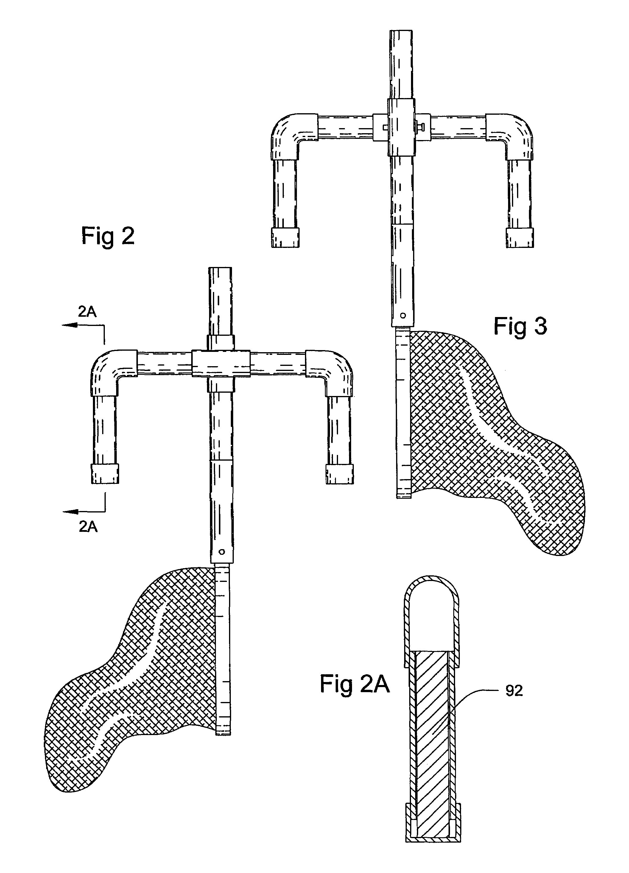
[0028]According to FIG. 1 this device consists of two sets of legs,...


PUM

PropertyMeasurementUnit
Timeaaaaaaaaaa
Timeaaaaaaaaaa
Heightaaaaaaaaaa

Abstract

This device will be available to the pool owner to clean the surface debris from a pool on a twenty-four hour seven day a week basis. It is free standing and can be moved from location to location around the perimeter of the pool depending on the pool. The ability to move it from location to location allows maximum efficiency to clean a pool. The device allows the net to be adjusted in a vertical direction to accommodate the varying level of water in the pool.

Description

CROSS REFERENCES TO RELATED APPLICATIONS[0001]Not ApplicableSTATEMENT REGARDING FEDERALLY SPONSORED RESEARCH[0002]Not ApplicableREFERENCE TO APPENDIX[0003]Not ApplicableBACKGROUND OF THE INVENTION[0004]A. Field of the Invention[0005]This device relates to the cleaning of the top surface of an in-ground or above ground pool on a continuous basis. The device uses a portable base to secure a pool net in one position in a pool.[0006]B. Prior Art[0007]Examples of the prior art in this area consist of devices, which are either secured to the side or lip of a pool by a clasp or bracket or are permanently attached to the deck or concrete of a pool perimeter. The Mongiello, U.S. Pat. No. 5,288,414 and McFarland, U.S. Pat. No. 5,173,181 are examples of these types of devices. While the above referenced patents have the ability to clean the top surface of the pool they are otherwise fixed in place and are not readily portable.[0008]In certain pools a particular area of the pool may be harder t...

Claims


Application Information

Patent Timeline
IPC IPC(8): E04H4/16
CPCE04H4/1254
Inventor GREATHEAD, JAMES
Owner GREATHEAD JAMES
Why Eureka
Try Eureka