Method and apparatus for non-contact electrostatic actuation of droplets

Inactive Publication Date: 2006-01-24
DUKE UNIV
View PDF29 Cites 221 Cited by
  • Summary
  • Abstract
  • Description
  • Claims
  • Application Information

AI Technical Summary

Benefits of technology

[0009]In general, the present invention provides an apparatus adapted for electrostatically actuating a droplet, and preferably an array of droplets, out from one plane to another plane (i.e., z-axis actuation). The apparatus generally comprises a first plane on which droplets are initially supplied, an elongate intermediate element spaced from the first plane, and a second plane spaced from the intermediate element that serves as the destination for actuated droplets. The first and second planes and the elongate intermediate element are rendered conductive to bring about and control the actuation of the droplet. Thus, the main structural portio

Problems solved by technology

While in situ synthesis can provide enormous densities, the technique is not suitable for rapid prototyping.
On the other hand, several problematic issues arise with regard to techniques relating to custom microarray printing technologies, including the size of the devices needed for sophisticated robotics, humidity and temperature control, the requirement of clean surroundings, wear and tear of the tips of pins or quills conventionally used, and expense of the equipment needed.
When employed to fabricate more than a few microarrays, the use of such contact techniques are undesirably slow processes.
Moreover, these techniques have created problems with uniformity in sample volume, equipment durability, and spot reproducibility.
While such non-contact array printing methods address some of the afore-mentioned problems relating to microarray printing, they do not solve all of them and add new problems of their own.
Keeping the inkjet orifices free of contaminants is one such problem.
Moreover, air bubbles can develop that impair reliability.
In addition, the size or footprint of the system can still be a problem.
While the device can be scaled to a small size, it is similar to inkjet devices and burdened by similar problems.

Method used


Image

  • Method and apparatus for non-contact electrostatic actuation of droplets
  • Method and apparatus for non-contact electrostatic actuation of droplets
  • Method and apparatus for non-contact electrostatic actuation of droplets

Examples


Embodiment Construction

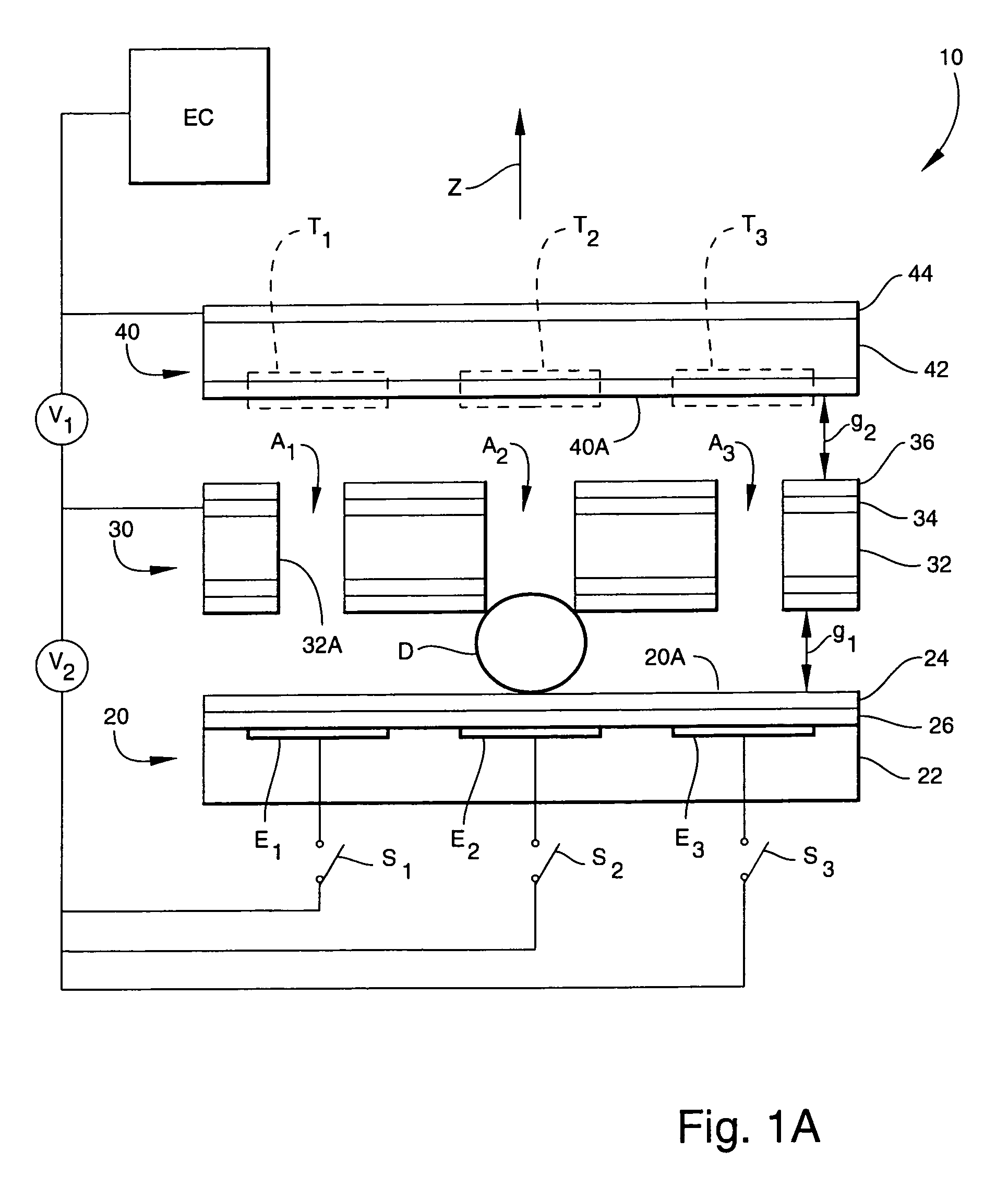
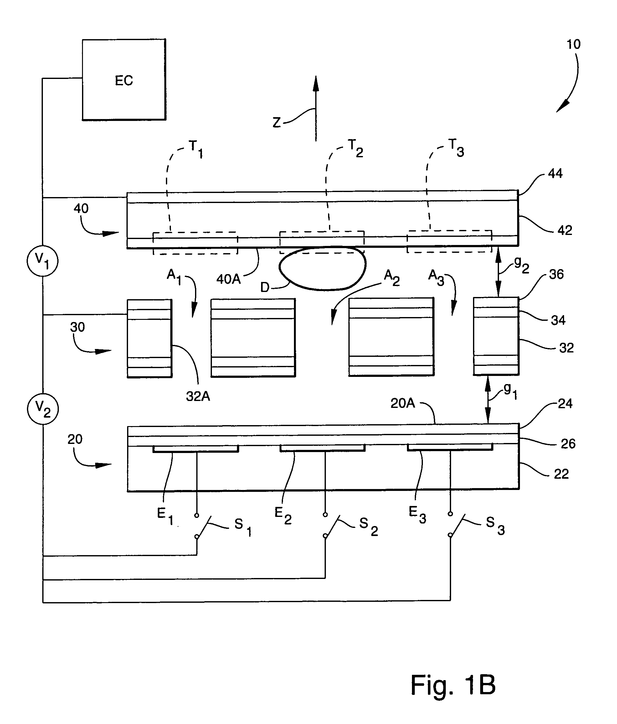
[0029]For purposes of the present disclosure, the terms “layer” and “film” are used interchangeably to denote a structure or body that typically is deposited on, formed on, coats, treats, or is otherwise disposed on another structure.

[0030]For purposes of the present disclosure, the term “communicate” (e.g., a first component “communicates with” or “is in communication with” a second component) is used herein to indicate a structural, functional, mechanical, optical, electrical, or fluidic relationship, or any combination thereof, between two or more components or elements. As such, the fact that one component is said to communicate with a second component is not intended to exclude the possibility that additional components may be present between, and / or operatively associated or engaged with, the first and second components.

[0031]For purposes of the present disclosure, it will be understood that when a given component such as a layer, region or substrate is referred to herein as b...


PUM

PropertyMeasurementUnit
Electric potential / voltageaaaaaaaaaa
Distanceaaaaaaaaaa
Distanceaaaaaaaaaa

Abstract

An apparatus for actuating a droplet comprises a first conductive layer, a second conductive layer, a conductive elongate element, and a voltage source. The first conductive layer comprises a first hydrophobic surface. The second conductive layer comprises a hydrophilic surface facing the first hydrophobic surface. The second conductive layer is axially spaced from the first conductive layer to define a gap therebetween. The conductive medial element is disposed in the gap between the first and second conductive layers, and comprises a second hydrophobic surface. The voltage source communicates with the second conductive layer and the elongate element. By applying a voltage potential between the elongate element and the second conductive layer, droplets can be electrostatically actuated so as to move from the first conductive layer into contact with the second conductive layer. The apparatus is particularly useful in the synthesis of microarrays of biological, chemical, or biochemical samples.

Description

GOVERNMENT INTEREST[0001]This invention was made with Government support under Grant No. F30602-98-2-0140 awarded by the Defense Advanced Research Projects Agency. The Government has certain rights in the invention.TECHNICAL FIELD[0002]The present invention is generally directed to the field of droplet actuation. More specifically, the present invention relates to non-contact, out-of-plane or z-axis, electrostatic actuation of droplets. A particularly advantageous application of the present invention relates to the fabrication of sample-containing microarrays.BACKGROUND ART[0003]Conventional techniques for in situ synthesis and custom microarray manufacturing have been developed in the field of biological, chemical, and biochemical assaying of samples (e.g., nucleic acids, proteins, pharmaceutical compounds, and other analytes of interest), for use in sample detection, monitoring, and analysis. For example, DNA microarray technology is currently being developed for use in genomic re...

Claims


Application Information

Patent Timeline
IPC IPC(8): C12Q1/68B01L3/02C12M1/36G01N15/05B05B5/025C40B60/14
CPCB01L3/0241B01J2219/0036B01J2219/0065B01J2219/00653B01L2200/0626C40B60/14B01L2400/027B01L2400/0415B01L2400/0427B05B5/0255B41J2002/14395B01L2300/089
Inventor KOLAR, PRAMODFAIR, RICHARD B.
Owner DUKE UNIV
Why Eureka
Try Eureka