
Object tracking

a technology of object tracking and tracking device, applied in the direction of instruments, electric signalling details, mechanical actuation of burglar alarms, etc., can solve the problems of signal collision potential and need a separate transceiver

Inactive Publication Date: 2006-01-24
FORWARD THINKING TRACKING LLC
View PDF9 Cites 86 Cited by
  • Summary
  • Abstract
  • Description
  • Claims
  • Application Information

AI Technical Summary

Benefits of technology

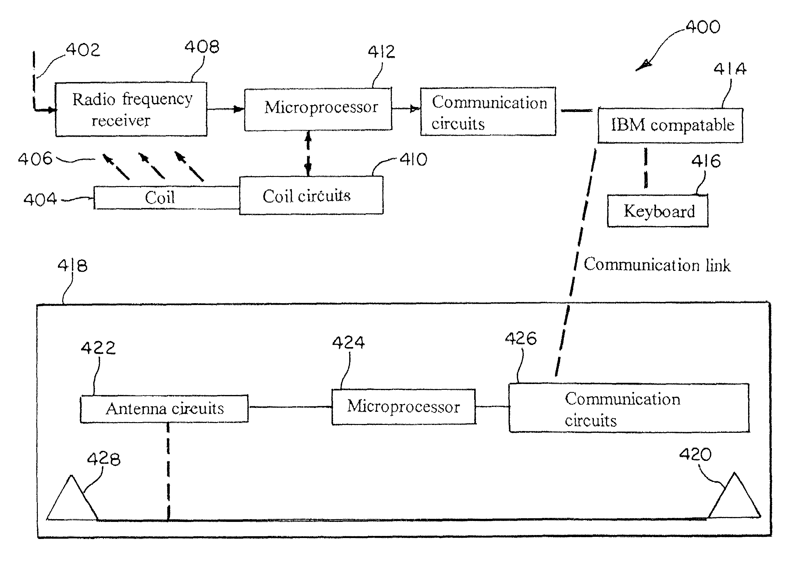
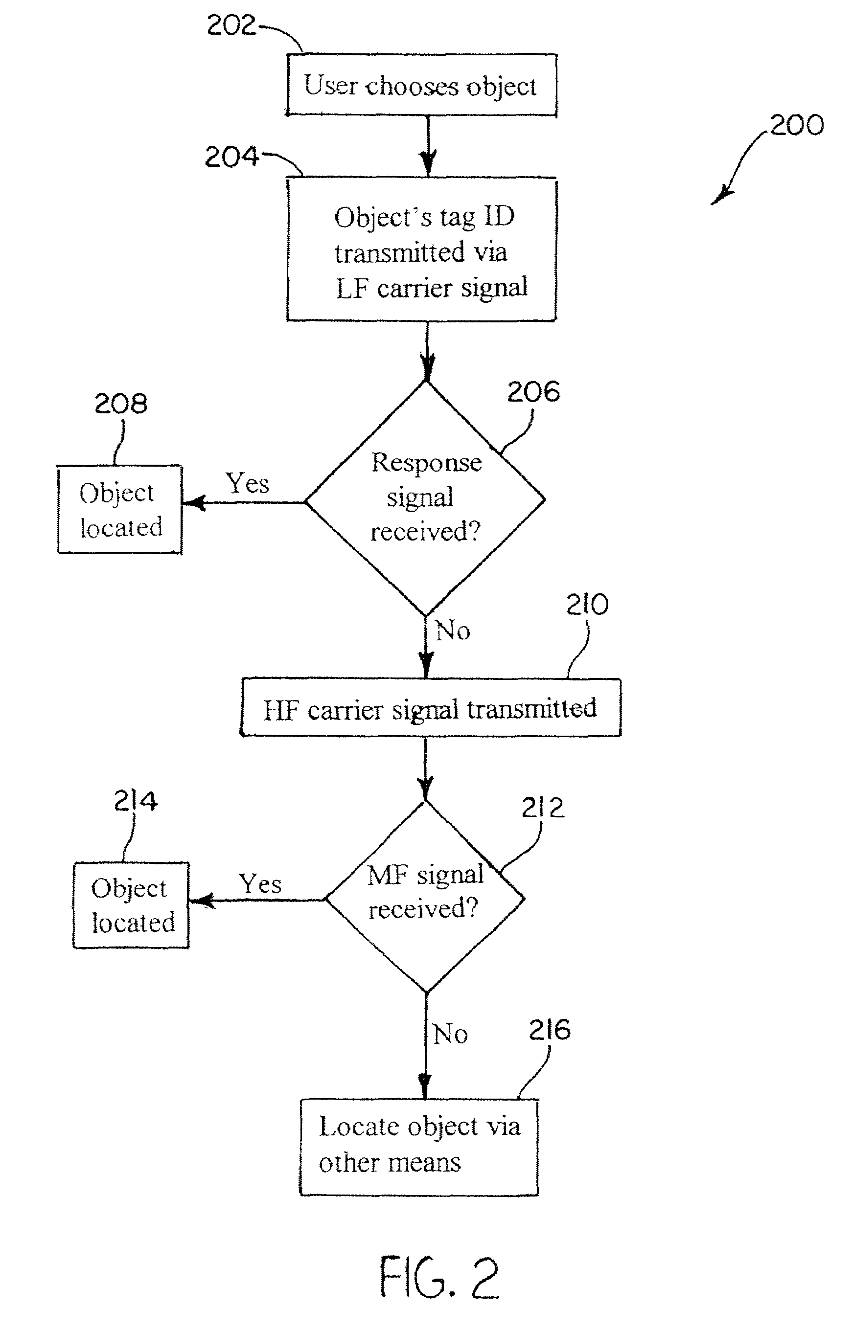
[0008]One advantage of the present invention is that a system and method of communicating with an object is provided that identifies and locates an object. Still another advantage of the present invention is that a system and method is provided that utilizes a low radio frequency signal and high radio frequency signal and triangulation to locate and communicate with the object. Other features and advantages of the present invention will be readily appreciated, as the same becomes better understood after reading the subsequent description taken in conjunction with the accompanying drawings.
is that a system and method of communicating with an object is provided that identifies and locates an object. Still another advantage of the present invention is that a system and method is provided that utilizes a low radio frequency signal and high radio frequency signal and triangulation to locate and communicate with the object. Other features and advantages of the present invention will be readily appreciated, as the same becomes better understood after reading the subsequent description taken in conjunction with the accompanying drawings.

Problems solved by technology

The system disclosed in Maloney is limited in that the system requires a plurality of receptacles and the RFID tags are only activated when the associated object is placed in a receptacle.
A second disadvantage of the system disclosed in Maloney is that it requires a separate transceiver for each storage receptacle within the storage box.
A third disadvantage of the system disclosed in Maloney is the potential for signal collision when multiple objects are put in the same receptacle.

Method used


Image

  • Object tracking
  • Object tracking
  • Object tracking

Examples


Embodiment Construction

[0015]In the following detailed description of the present invention, reference is made to the accompanying Drawings, which form a part hereof, and in which are shown by way of illustration specific embodiments in which the present invention may be practiced. It should be understood that other embodiments may be utilized and structural changes may be made without departing from the scope of the present invention.

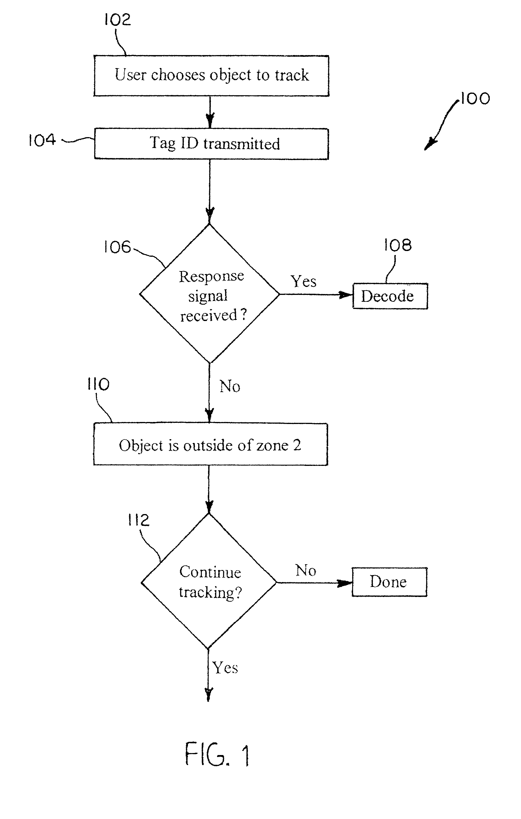
[0016]The present invention provides capabilities for tracking many different kinds of objects in many different applications. According to the present invention, each object to be tracked has an E-Tag attached to it. Each E-Tag comprises electronics that allow the tag to have wireless communication with a base station as described herein. Thus, E-Tags have associated with them a unique ID (“tag ID”) that uniquely identifies the E-Tag and, therefore, uniquely identifies the object to which the E-Tag is attached. Each E-Tag may also have other data stored on it that is associ...


PUM


Abstract

Methods and systems for tracking objects. Systems of the present invention include a base station capable of transmitting and receiving signals at multiple frequencies. Each object to be tracked has attached to it what for the purpose of the present specification is referred to as an electronic tag (“E-Tag”). Each E-Tag can transmit signals that can be received and interpreted by the base station and each E-Tag can receive and interpret signals transmitted by the base station. The transmitting (and receiving) of signals between the base station and an E-Tag allows the base station to track the E-Tag, and therefore, track the object to which the E-Tag is attached. Methods utilized to track objects in accordance with the present invention vary depending on the distance of the object from a base station (“range” of the object). The distances from the base station are divided into zones with the lowest numbered zone (that is, zone 1) being closest to the base station and the highest numbered zone being farthest away from the base station. Typically, embodiments of the present invention are adapted to track objects in four different zones. LF and HF communications can be utilized to track objects in zones 1 and 2, triangulation can be used to track objects in zone 3, and global location techniques can be utilized to track objects in zone 4. In a typical application, zone 1 covers a storage enclosure such as a desk drawer, a file cabinet, or a safe for example. Zone 2 frequently covers a room or a building, zone 3 covers up to the maximum distance for which triangulation technology can be used to track an object, and zone 4 covers the maximum distance for which global location techniques can be used to track an object.

Description

FIELD OF THE INVENTION[0001]The present invention relates generally to object tracking. More specifically, the present invention relates to the use of RFID technology and triangulation technology to track objects at varying distances from a source.BACKGROUND OF THE INVENTION[0002]Various types of systems and methodologies are known in the art for tracking items. Tracking an item may involve locating or identifying a stationary object (a car key, book, or file, for example) that has been temporarily misplaced. One example of such a system is referred to as an inventory control system. When the object is valuable, such as with jewelry, or the key to a vehicle, it may be desirable to control access to the object, or to locate the object within a predetermined area. Tracking can also involve a continuous monitoring of a moving object (personnel or vehicles, for example) over a period of time.[0003]It is known in the art to utilize radio frequency identification (“RFID”) technology for t...

Claims


Application Information

Patent Timeline
IPC IPC(8): G08B26/00G08B13/14
CPCG08B21/0227G08B13/1427
Inventor KENNY, THOMASCHAWLA, RAJPACSAI, ERNESTSZASZ, CARLGILLING, ROBERTMARQUARDT, THOMAS
Owner FORWARD THINKING TRACKING LLC
Learn More