Apparatus and method for downhole well equipment and process management, identification, and actuation

Inactive Publication Date: 2006-01-24
SCHLUMBERGER TECH CORP
View PDF71 Cites 94 Cited by
  • Summary
  • Abstract
  • Description
  • Claims
  • Application Information

AI Technical Summary

Benefits of technology

[0012]The present invention has several benefits over prior art apparatus and methods. It provides a way of selectively installing, actuating, or inventorying downhole equipment at a desired time and/or at a desired location, at lower cost and with greater flexibility than in prior art techniques.
[0013]Another benefit of the present invention lies in the reduction of downhole tool manipulation time. In some cases

Problems solved by technology

In the past, rather complex means have been used to determine when a given piece of downhole equipment is in the desired location in the wellbore.
These methods have often been impr

Method used


Image

  • Apparatus and method for downhole well equipment and process management, identification, and actuation
  • Apparatus and method for downhole well equipment and process management, identification, and actuation
  • Apparatus and method for downhole well equipment and process management, identification, and actuation

Examples


Embodiment Construction

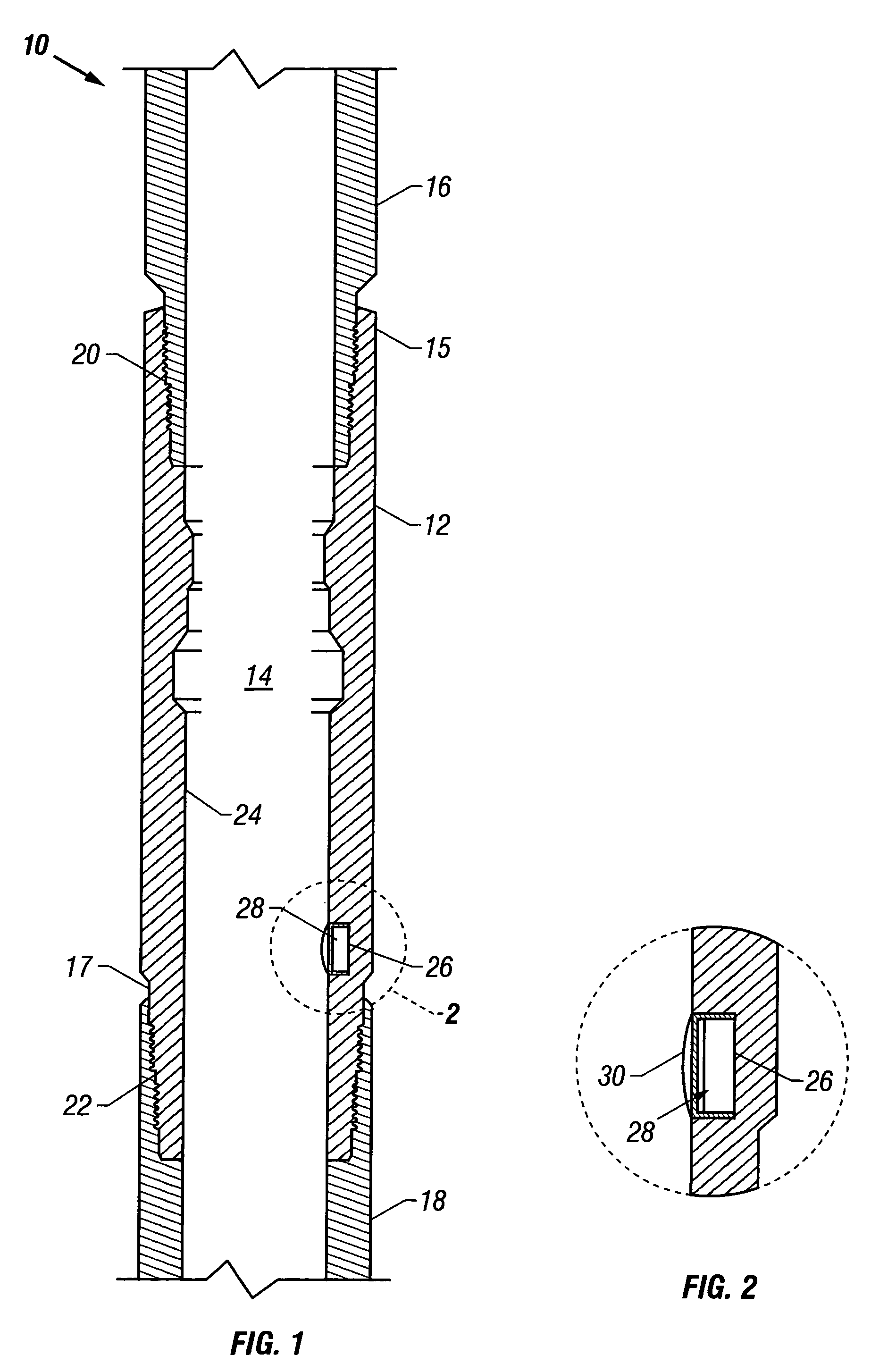
[0034]The present invention makes use of non-acoustic transmission, such as radio frequency transmission, optical transmission, tactile transmission, or magnetic transmission of at least one identification code to locate, install, actuate, and / or manage downhole equipment in a subterranean wellbore. FIG. 1 shows one embodiment of the invention. A segment of a tubing string 10 includes a first downhole structure 12, which in this embodiment is a landing nipple that has a hollow axial bore 14 therethrough. The landing nipple 12 is attached at its upper end 15 to an upper tubular member 16, and at its lower end 17 to a lower tubular member 18, by threaded connections 20 and 22. The landing nipple 12 has an inner diameter 24 that is defined by the inner surface of the nipple wall. A recess 26 is formed in the inner surface of the nipple wall, and a non-acoustic transmitter unit, in this case a radio frequency identification transmitter unit 28, is secured therein. The non-acoustic frequ...


PUM


Abstract

A method for actuating or installing downhole equipment in a wellbore employs non-acoustic signals (e.g., radio frequency signals) to locate, inventory, install, or actuate one downhole structure in relation to another downhole structure. The method comprises the steps of: (a) providing a first downhole structure that comprises a non-acoustic (e.g., radio frequency) identification transmitter unit that stores an identification code and transmits a signal corresponding to the identification code; (b) providing a second downhole structure that comprises a non-acoustic receiver unit that can receive the signal transmitted by the non-acoustic identification transmitter unit, decode the signal to determine the identification code corresponding thereto, and compare the identification code to a preset target identification code; wherein one of the first downhole structure and the second downhole structure is secured at a given location in a subterranean wellbore, and the other is moveable in the wellbore; (c) placing the second downhole structure in close enough proximity to the first downhole structure so that the non-acoustic receiver unit can receive the signal transmitted by the non-acoustic identification transmitter unit; (d) comparing the identification code determined by the non-acoustic receiver unit to the target identification code; and (e) if the determined identification code matches the target identification code, actuating or installing one of the first downhole structure or second downhole structure in physical proximity to the other.

Description

[0001]This application is a continuation-in-part of U.S. application Ser. No. 09 / 536,953, filed Mar. 28, 2000.TECHNICAL FIELD OF THE INVENTION[0002]This invention relates to the equipment and methods used in the drilling and completion of wells, such as oil and gas wells, and in the production of fluids from such wells.BACKGROUND OF THE INVENTION[0003]Hydrocarbon fluids such as oil and natural gas are obtained from a subterranean geologic formation (i.e., a “reservoir”) by drilling a well that penetrates the hydrocarbon-bearing formation. Once a wellbore has been drilled, the well must be “completed” before hydrocarbons can be produced from the well. A completion involves the design, selection, and installation of tubulars, tools, and other equipment that are located in the wellbore for the purpose of conveying, pumping, or controlling the production or injection of fluids. After the well has been completed, production of oil and gas can begin.[0004]Each of these phases (drilling, c...

Claims


Application Information

Patent Timeline
IPC IPC(8): G01V3/00E21B23/00E21B23/02E21B31/00E21B34/06E21B41/00E21B43/119E21B47/024E21B47/09E21B47/12G01S13/74G01V15/00
CPCE21B23/00G01V15/00E21B31/00E21B34/06E21B41/00E21B41/0035E21B43/119E21B47/00E21B47/024E21B47/04E21B47/09E21B47/12E21B47/124G01S13/74E21B23/02E21B2023/008E21B23/001E21B47/26
Inventor THOMEER, HUBERTUS V.ADNAN, SARMADSHEFFIELD, RANDOLPH J.KENISON, MICHAEL H.FORBES, KEVIN J.
Owner SCHLUMBERGER TECH CORP
Why Eureka
Try Eureka