Self-routing data switching system

a data switching and self-routing technology, applied in the field of data switching systems, can solve the problems of complex switching control units, difficult to achieve output buffering, and other problems, and achieve the effect of exempting from using a cost-inefficient central control uni

Active Publication Date: 2006-01-24
NAT TAIWAN UNIV
View PDF6 Cites 7 Cited by
  • Summary
  • Abstract
  • Description
  • Claims
  • Application Information

AI Technical Summary

Benefits of technology

[0003]An object of the present invention is to provide a data switchi...

Problems solved by technology

The output buffering, however, is difficult to be achieved under the current hardware environment where the maximum transmission speed inside the...

Method used


Image

  • Self-routing data switching system
  • Self-routing data switching system
  • Self-routing data switching system

Examples


Embodiment Construction

[0037]The present invention will now be described more specifically with reference to the following embodiments. It is to be noted that the following descriptions of preferred embodiments of this invention are presented herein for purpose of illustration and description only; it is not intended to be exhaustive or to be limited to the precise form disclosed.

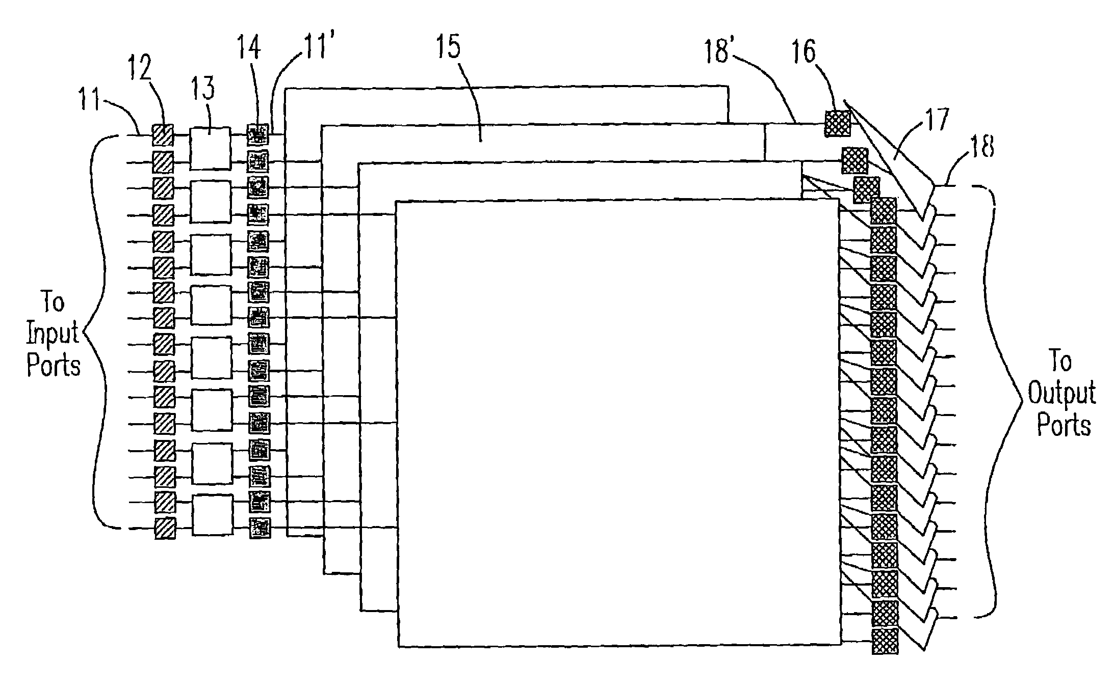
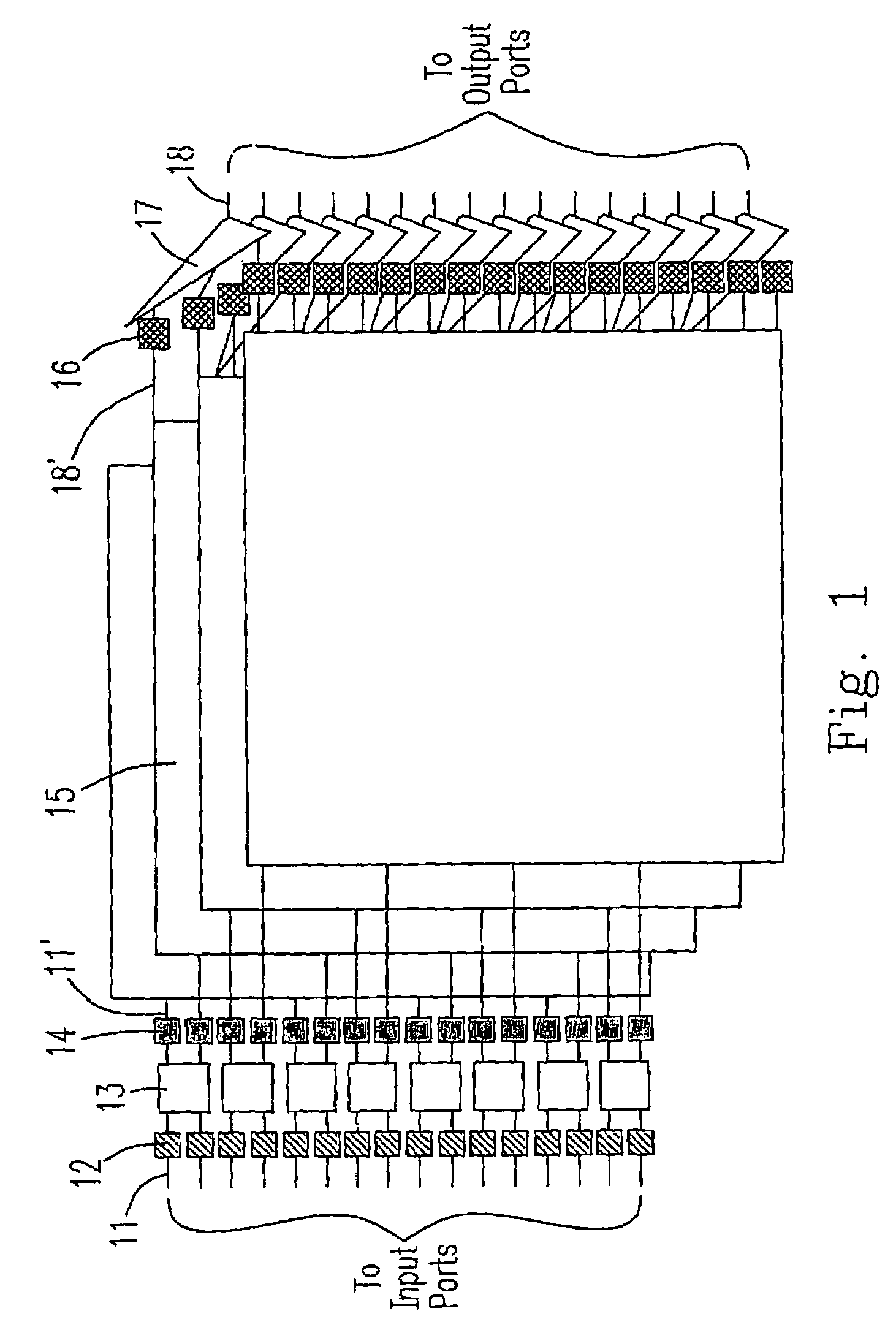
[0038]Please refer to FIG. 1 which is a schematic diagram showing a preferred embodiment of a data switching system according to the present invention. The exemplified system is a 16×16 switch performing switching functions between sixteen input ports and sixteen output ports. The system includes sixteen first input terminals 11, sixteen line-cards 12, eight pre-processors 13, sixteen time sequencers 14, sixteen second input terminals 11′, four switching matrix planes 15, sixty-four output buffers 16, sixteen multiplexers 17, sixteen first output terminals 18 and sixteen second output terminals 18′, which are interconnected as sh...


PUM


Abstract

A self-routing data switching system is disclosed. The data switching system includes a plurality of repetitive switching matrix planes, each of which is electrically connected between a less number of input terminals and a larger number of output terminals, thereby reducing the head-of-line blocking effect. Each switching matrix plane includes a switching element array interconnected between the input ports and the output ports for determining whether the data packet from an input port can be transmitted to a designated output port. The data switching system further includes a plurality of pre-processors to manage the input timing of data packets into the switching matrix array in order to avoid output conflict.

Description

FIELD OF THE INVENTION[0001]The present invention relates to a data switching system, and more particularly to a self-routing data switching system.BACKGROUND OF THE INVENTION[0002]With the rapid growth of internet traffic load and the development of optical-fiber communication technology, the requirements on switches are getting more and more in order to avoid switches becoming bottlenecks for data transmission. For example, for a conventional input-buffering switch, blocking probability is relatively high, compared to an output-buffering one. The output buffering, however, is difficult to be achieved under the current hardware environment where the maximum transmission speed inside the switch is limited. As known, for output buffering, the transmission rate inside the switch has to be several times of that of the external transmission line. On the other hand, in order to minimize the head-of-line blocking effect of an input-buffering switch, various architectures were developed to...

Claims


Application Information

Patent Timeline
IPC IPC(8): H04Q11/00H04L12/56
CPCH04L49/25H04L49/101H04L49/1523H04L49/3027H04L49/254H04L49/3018
Inventor WU, JINGSHOWNCHEN, KUN-TSOTSAO, HEN-WAI
Owner NAT TAIWAN UNIV
Why Eureka
Try Eureka