
Method and apparatus for redundant transmission over TDMA optical networks

Inactive Publication Date: 2006-01-24
GOOGLE TECH HLDG LLC
View PDF27 Cites 1 Cited by
  • Summary
  • Abstract
  • Description
  • Claims
  • Application Information

AI Technical Summary

Benefits of technology

[0003]It would be advantageous to provide protection in an optical network with minimal data loss and without requiring extensive data buffering.
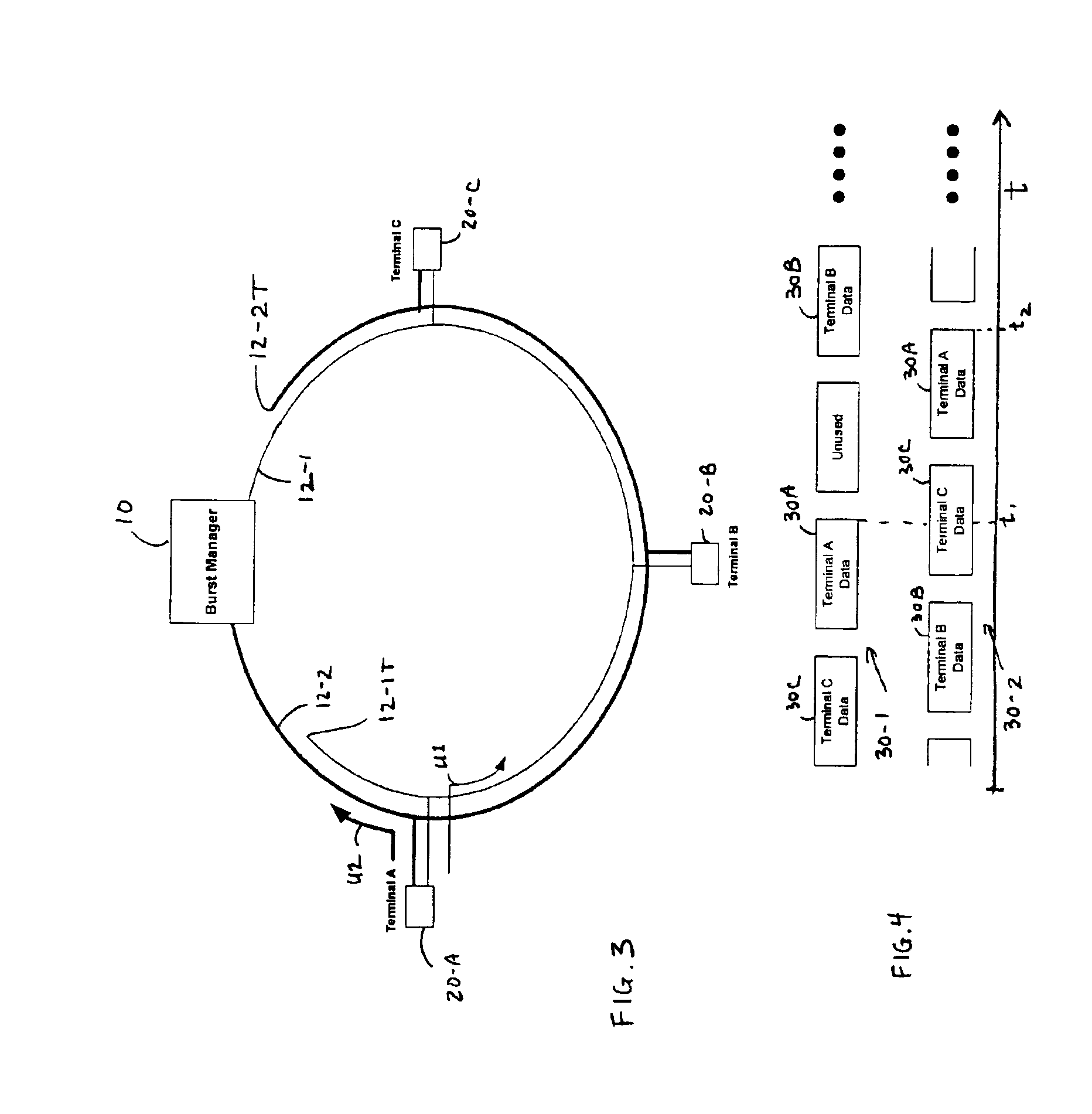
[0004]The approach of the present method and apparatus provides efficient and fast recovery on a timeslot basis of redundant data transmitted from remote terminals to a burst manager in a passive optical network or other network using TDMA. This approach can be used in a full or half-duplex mode and with multiple wavelengths.

Problems solved by technology

Otherwise, the transmissions from two or more devices could collide at some common point in the network, causing loss of data.
Such buffering adds undesirable complexity and latency to the system.
Most often, communication systems incur data loss for some period of time, e.g., 50 ms in a SONET network, prior to recovering full error-free transmission.

Method used


Image

  • Method and apparatus for redundant transmission over TDMA optical networks
  • Method and apparatus for redundant transmission over TDMA optical networks
  • Method and apparatus for redundant transmission over TDMA optical networks

Examples


Embodiment Construction

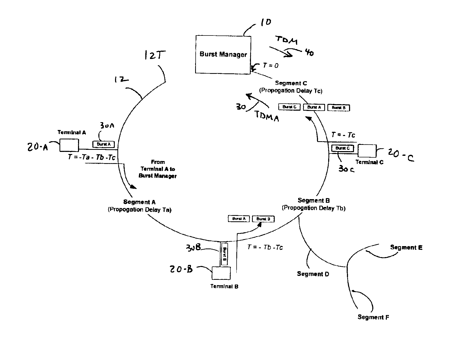
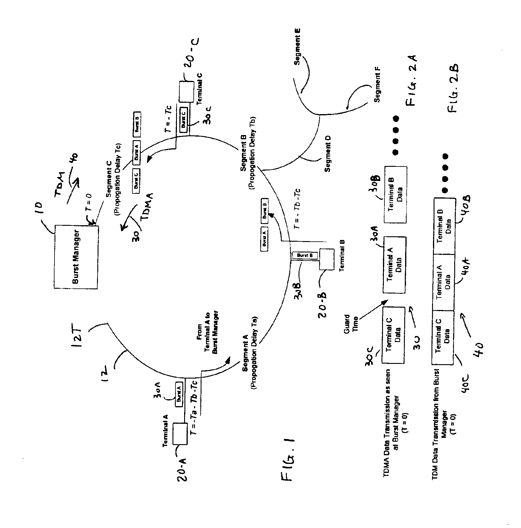
[0025]Transmission from multiple devices, wherein each device is located at a different physical distance (in a range from a few feet to many miles apart), can be provided using TDMA. A TDMA access technique requires that each device that transmits does so by bursting its information onto a common physical medium at a specifically assigned time. Transmitted signals from different physical devices are received without collision by a central terminal, also referred to as a burst manager, by allocating specific non-overlapping timeslots to each device and by offsetting the bursts, in time, to account for the difference in propagation delay between devices. Otherwise, the transmissions from two devices could collide at some common point in the network, causing loss of data.

[0026]FIG. 1 shows a single network which illustrates transmission in a typical passive optical network (PON). For simplicity, three remote terminals 20-A, 20-B, 20-C are shown in the network connected to a burst mana...


PUM


Abstract

Communication between a burst manager and plural remote terminals over a first passive optical network (PON) and a second PON, with each PON having a downstream portion and an upstream portion, includes transmitting a common synchronization signal from the burst manager to the plural remote terminals over both downstream PON portions and transmitting burst data from the plural remote terminals over both upstream PON portions to the burst manager. The burst data for each remote terminal is delayed on the first and second PONs by corresponding first and second delays. The first delay includes a first ranging delay and the second delay includes a second ranging delay wherein the first and second ranging delays for each remote terminal are adjusted with respect to the common synchronization signal such that the burst data for any particular remote terminal transmitted on the first PON arrives at the burst manager simultaneously with the burst data for that particular remote terminal transmitted on the second PON in the same relative timeslot position.

Description

BACKGROUND OF THE INVENTION[0001]In a time division multiple access (TDMA) optical system which comprises multiple optical devices transmitting toward a single optical receiver, each optical device transmits by bursting its information onto the common physical medium. Transmissions from different sources are made possible by offsetting, in time, the burst from each device so that none of the bursts overlaps, in time, with any other burst from any source. Otherwise, the transmissions from two or more devices could collide at some common point in the network, causing loss of data. The time allocated for a single burst of data from a given transmitter is referred to as a “timeslot”.[0002]In the current network environment, telecommunications service providers typically deploy services using SONET / SDH add / drop multiplexers. To provide redundancy protection, the SONET / SDH elements are arranged in ring configurations which provide line or path protection switching. In such protection swit...

Claims


Application Information

Patent Timeline
IPC IPC(8): H04J3/06H04L12/28H04L25/40H04L7/02H04B10/00
CPCH04Q11/0067Y10S370/907H04Q2011/0081
Inventor MASUCCI, JEFFREY A.
Owner GOOGLE TECH HLDG LLC
Learn More