
Data compression device and compression method

a data compression and data technology, applied in the field of data processing technologies, can solve the problems of increasing the number of units required, increasing the cost, increasing the size of the unit, etc., and achieve the effect of greatly reducing the distortion ra

Active Publication Date: 2021-11-25
TCL CHINA STAR OPTOELECTRONICS TECH CO LTD
View PDF0 Cites 2 Cited by
  • Summary
  • Abstract
  • Description
  • Claims
  • Application Information

AI Technical Summary

Benefits of technology

This patent introduces a data compression device and method that can simultaneously meet a distortion rate and a compression ratio, which is a technical improvement over existing methods. The device uses a quantization table processing unit to determine a target quantization table that optimizes distortion and compression, and a quantization unit to perform quantization and compression processing on the data. By constructing different quantization tables for different data, distortion is greatly reduced while meeting the compression ratio. This method helps to improve data compression efficiency and minimize data loss.

Problems solved by technology

As a resolution of the liquid crystal panel increases, a storage unit required to compensate data becomes larger and larger, the cost is also higher and higher, and compensation data needs to be compressed.
However, lossless compression usually has a low compression ratio and cannot achieve compression requirements.
Lossy compression has a high compression ratio, but distortion is more serious after the data is compressed.
Therefore, the existing data compression method has issues that the distortion rate and the compression ratio cannot be simultaneously satisfied and needs to be improved.

Method used

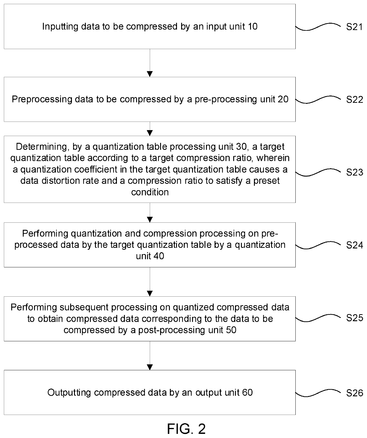
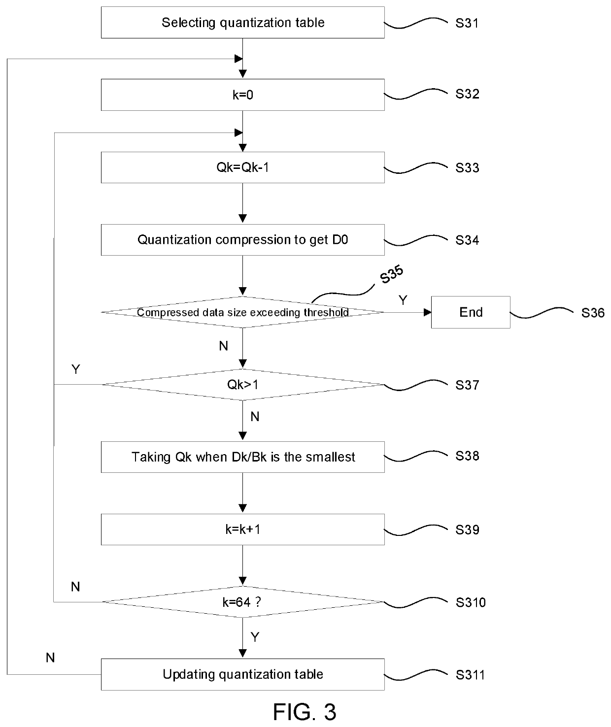

Image

  • Data compression device and compression method
  • Data compression device and compression method
  • Data compression device and compression method

Examples


Embodiment Construction

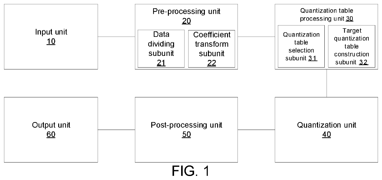
[0032]The following description of the various embodiments is provided to illustrate the specific embodiments of the present invention. The directional terms mentioned in the present application, such as up, down, front, back, left, right, inside, outside, side, etc., are only directions referring to the additional drawings. Therefore, the directional terminology used is for the purpose of illustration and understanding and is not intended to be limiting. In the figures, structurally similar elements are denoted by the same reference numerals.

[0033]Aiming at issues of low compression rate and severe distortion existing in existing compression methods of compensation data, the present application provides a data compression device and a compression method to alleviate the issues.

[0034]In an embodiment, as shown in FIG. 1, a data compression device provided by the embodiment of the present application includes:

[0035]An input unit 10 configured to input original data to be compressed.

[...


PUM


Abstract

A data compression device and a compression method are provided. The data compression device includes a quantization table processing unit and a quantization unit. The quantization table processing unit determines a target quantization table in which a quantization coefficient satisfies a data distortion rate and a compression ratio of a preset condition according to a target compression ratio. By constructing different quantization tables for different data, a distortion rate is greatly reduced based on satisfying a compression ratio, and issues that the distortion rate and the compression ratio cannot be simultaneously satisfied in the prior art are alleviated.

Description

FIELD OF INVENTION[0001]The present disclosure relates to the field of data processing technologies, and more particularly to a data compression device and a compression method.BACKGROUND OF INVENTION[0002]In current displays, compensation algorithms are often used to compensate for uneven display performance of liquid crystal panels. As a resolution of the liquid crystal panel increases, a storage unit required to compensate data becomes larger and larger, the cost is also higher and higher, and compensation data needs to be compressed.[0003]Existing compression processing of compensation data includes lossy compression and lossless compression. However, lossless compression usually has a low compression ratio and cannot achieve compression requirements. Lossy compression has a high compression ratio, but distortion is more serious after the data is compressed.[0004]Therefore, the existing data compression method has issues that the distortion rate and the compression ratio cannot ...

Claims


Application Information

Patent Timeline
Patent Type & Authority Applications(United States)
IPC IPC(8): G06T9/00G06T3/40H04N19/85H04N19/126H04N19/119H04N19/625H04N19/91
CPCG06T9/00G06T3/40H04N19/85H04N19/91H04N19/119H04N19/625H04N19/126H04N19/42H04N19/124H04N19/186H04N19/184H04N19/147H04N19/172
Inventor ZHU, JIANG
Owner TCL CHINA STAR OPTOELECTRONICS TECH CO LTD
Learn More