Image forming apparatus and driving device for image carrying member with banding suppression

a technology of banding suppression and forming apparatus, which is applied in the direction of rotating vibration suppression, shafts and bearings, instruments, etc., can solve the problems of unavoidable large size of the apparatus, inability to sufficiently stabilize the velocity of the rotation body, such as the belt, and increase in cost, so as to suppress or prevent the formation of an image defect, no increase in size, and stabilize the velocity of the image

Inactive Publication Date: 2006-01-24
FUJIFILM BUSINESS INNOVATION CORP
View PDF5 Cites 14 Cited by
  • Summary
  • Abstract
  • Description
  • Claims
  • Application Information

AI Technical Summary

Benefits of technology

[0016]The invention is to solve the aforementioned problems associated with the conventional techniques and to provide such a driving device for an image carrying member, e.g., a belt, that causes no increase in size and cost of the device and sufficiently stabilizes the velocity of the image carrying member such as a belt, upon fluctuation in load, so as to suppress or prevent formation of an image defect referred to as so-called “banding”.
[0017]The driving device for an image carrying member for rotationally driving the image carrying member by transmitting a rotational driving force to the image carrying member according to the invention contains, in one aspect, a rotating member rotating in contact with at least one of a driving force transmitting member and the image carrying member, which are arranged in a driving force transmission path for transmitting the driving force to the image carrying member, the rotating member rotating in contact with the driving force transmitting member or the image carrying member, and providing, upon occurring fluctuation in velocity of the driving force transmitting member or the image carrying member, a viscous effect that suppresses the fluctuation in velocity.

Problems solved by technology

However, the aforementioned conventional techniques contain the following problems.
In the case of the image transferring apparatus described in JP-A-9-292778, a flywheel is attached to at least one of pivots of a driving roll and a driven roll through a torsional elastic body, and therefore, it has such a problem in that the apparatus unavoidably becomes large sized and suffers increase in cost due to the flywheel attached.
In the case of the driving device for a rotation body described in JP-A-7-140842, a rotation body and a driving gear are connected with an elastic member or a viscoelastic member, and therefore, it has such a problem in that the velocity of the rotation body, such as a belt, cannot be sufficiently stabilized upon fluctuating in load due to influence on elastic deformation of the elastic body or the viscoelastic body.
Furthermore, there is a common problem in the techniques described in JP-A-9-292778 and JP-A-7-140842.
However, with respect to a resonance point ascribed to torsional rigidity of a belt and a driven roll stretching the belt, i.e., in the case where a resonance point outside the driving system comes into an issue, the techniques do not directly act on the belt, and therefore, sufficient effect is difficult to be obtained for stabilizing the velocity of the belt.
The resonance point outside the driving system is often present in a frequency range of from several tens to 100 Hz, and causes such severe problems in that it is liable to agree with the engaging frequency of the gear driving system, and the banding occurs in this frequency range, which is liable to be recognized as a defect in image quality due to the characteristics of human vision.
As a result, no sufficient effect is obtained in stabilizing the velocity of the belt, and such a problem remains in that banding that is liable to be recognized as a defect in image quality cannot be effectively prevented.

Method used


Image

  • Image forming apparatus and driving device for image carrying member with banding suppression
  • Image forming apparatus and driving device for image carrying member with banding suppression
  • Image forming apparatus and driving device for image carrying member with banding suppression

Examples


embodiment 1

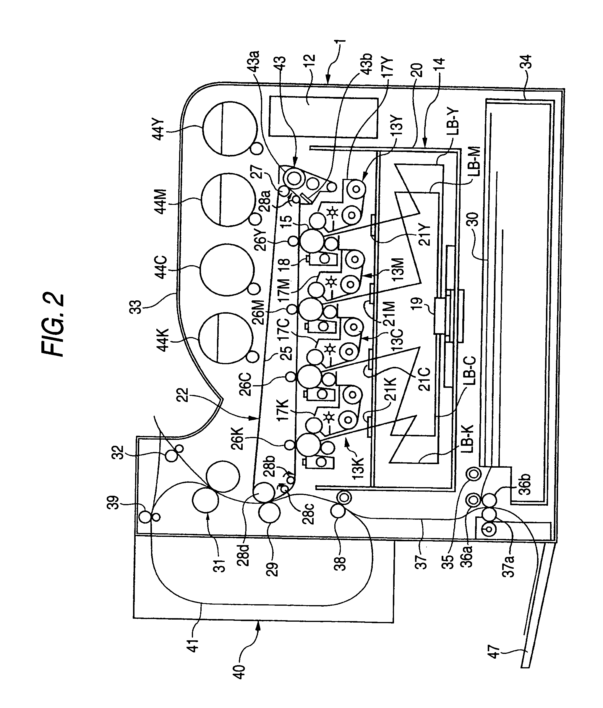
[0039]FIG. 2 shows a tandem digital color printer as an image forming apparatus, to which a driving device for an image carrying member according to Embodiment 1 of the invention is applied. FIG. 3 shows a tandem digital color duplicator as an image forming apparatus, to which a paper feeding device according to the Embodiment 1 of the invention is applied.

[0040]In FIGS. 2 and 3, numeral 1 denotes a main body of a tandem digital color printer or duplicator, and in the case of the digital color duplicator, an automatic document feeder (ADF) 3 for automatically feeding a document 2 in the form of a sole sheet separated from another, and a document reading device 4 for reading an image of the document 2 fed by the automatic document feeder 3 are arranged in an upper part of the main body 1 as shown in FIG. 3. In the document reading device 4, the document 2 placed on a platen glass 5 is illuminated with a light source 6, and an image reading element 11, such as a CCD, is scan-exposed w...

experimental example 1

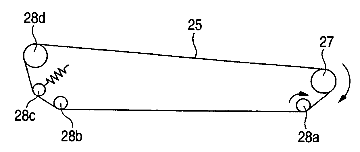
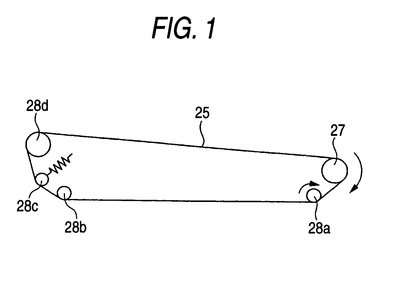
[0074]In order to confirm the effect of the invention, the inventors have measured fluctuation in velocity of the driving roll 27 for rotationally driving the intermediate transfer belt 25 in the color image forming apparatus shown in FIGS. 1 and 2, and also have measured the transfer function characteristics of the driving system from the driving motor 53 to the driving roll 27 as shown in FIG. 5.

[0075]FIGS. 7 and 8 are graphs showing the results of the aforementioned measurements. The ordinate in FIG. 7 indicates the value obtained by FFT analysis of the fluctuation in rotation velocity of the driving roll 27. The ordinate in FIG. 8 indicates the value showing a magnitude of the transfer function.

[0076]It is understood from FIGS. 7 and 8 that the decay area appears in a large range of from 3 to 100 Hz on the transfer function characteristics of the driving system, and the peaks having significantly appeared as fluctuation in velocity are disappeared to provide rotational driving o...

experimental example 2

[0077]The inventors have conducted such an experiment using the color image forming apparatus shown in FIGS. 1 and 2 in that the change of the dynamic load torque of the driving roll is observed in the case where the rotation velocity of the damper roll 28a is changed.

[0078]FIG. 9 is a graph showing the results of the experiment.

[0079]It is understood from FIG. 9 that the load torque of the driving roll 27 has such characteristics that it increases in the case where the peripheral velocity differential between the damper roll 28a and the intermediate transfer belt 25 is negative (i.e., the damper roll 28a has a negative velocity) and decreases in the case where the peripheral velocity differential is positive (i.e., the damper roll 28a has a positive velocity), with the point of zero peripheral velocity differential, where the velocity of the damper roll 28a agrees with the velocity of the intermediate transfer belt 25, as the inflection point. The change in load torque with respect...


PUM


Abstract

A driving device for an image carrying member, e.g., a belt, is to be provided that causes no increase in size and cost of the device and sufficiently stabilizes the velocity of the image carrying member upon fluctuation in load, so as to suppress or prevent formation of an image defect referred to as so-called “banding”. A rotating member is made in contact with at least one of a driving force transmitting member and an image carrying member, which are arranged in a driving force transmission path for transmitting the driving force to the image carrying member, and the rotating member rotates in contact with the driving force transmitting member or the image carrying member, and providing, upon occurring fluctuation in velocity of the driving force transmitting member or the image carrying member, a viscous effect that suppresses the fluctuation in velocity.

Description

BACKGROUND OF THE INVENTION[0001]1. Field of the Invention[0002]The present invention relates to an image forming apparatus and a driving device used in an image forming apparatus.[0003]2. Description of the Related Art[0004]According to the conventional techniques, a color image forming apparatus, such as a color duplicator, a color printer and a color facsimile adapting this electrophotographic system, is constituted, for example, in the manner shown in FIG. 17. That is, plural photoreceptor drums 101Y, 101M, 101C and 101K for forming toner images of yellow, magenta, cyan and black are arranged along a lower surface (or an upper surface) of an endless intermediate transfer belt 100, and charging units, exposing units, developing units and the like, which are not shown in the figure, are arranged around the respective photoreceptor drums 101Y, 101M, 101C and 101K. The toner images of yellow, magenta, cyan and black formed on the photoreceptor drums 101Y, 101M, 101C and 101K are seq...

Claims


Application Information

Patent Timeline
Patent Type & Authority Patents(United States)
IPC IPC(8): G03G15/00G03G15/01G03G21/00F16C13/00F16F15/10F16F15/16G03G15/16
CPCG03G15/754G03G15/757G03G2215/0119
Inventor MITAMURA, YOSHIHIKOKIBAYASHI, SUSUMUHOKARI, NORIO
Owner FUJIFILM BUSINESS INNOVATION CORP
Why Eureka
Try Eureka