Check patentability & draft patents in minutes with Patsnap Eureka AI!

Mechanism for switching between closed and open center hydraulic systems

a hydraulic system and hydraulic system technology, applied in the direction of metal-working hand tools, servomotor components, servomotors, etc., can solve the problems of unsatisfactory or economically restrictive maintenance of both types of power sources, duplicate sets of tools, and substantial capital investment, and achieve the effect of convenient tool operation

Active Publication Date: 2006-01-31
GREENLEE TEXTRON
View PDF16 Cites 14 Cited by
  • Summary
  • Abstract
  • Description
  • Claims
  • Application Information

AI Technical Summary

Benefits of technology

[0016]A primary object of the invention is to provide a mechanism for a tool which provides for easier operation of the tool in an open-center or closed-center hydraulic system than other such tools of the prior art.
[0018]Another object of the invention is to provide a tool which is configured to operate in either an open-center or closed-center hydraulic system where the parts required for adjusting the tool between the open-center and closed-centers are low in number and cost.
[0020]Yet another object of the invention is to provide a novel hydraulic fluid flow mechanism for use with a hydraulic tool which allows the tool to be converted for use with a constant volume system to a constant pressure system and vice-versa, without the disassembly or removal of any parts from the tool.
[0022]Another object of the invention is to provide a novel hydraulic fluid flow mechanism based on a generally available and understood hydraulic tool thereby providing a hydraulic tool which can be used with either a constant volume system or a constant pressure system without requiring additional training or the maintenance of such a hydraulic tool.

Problems solved by technology

Typically, it is undesirable or economically restrictive to maintain both types of power sources in each field location.
Providing duplicate sets of tools, however, represents a substantial capital investment as well as storage and maintenance costs even though it overcomes the problems associated with having only one type of hydraulic power system.
Further, maintaining duplicate sets of tools requires additional space and additional training to make sure that the proper tool is used with the proper type of hydraulic system.
Some devices, such as trucks, however, are provided with only one type of hydraulic system and therefore this may not be a feasible solution.
This, however, would require that duplicate spools be available for use with each tool, again requiring additional inventory and storage costs as well as space requirements.
Another problem arises in that the frequent removal and replacement of the valve spools will also unnecessarily disturb the hydraulic system and seals and produce increased tool wear and the opportunity for the introduction of dirt and debris into the hydraulic system.
Thus, there is still the possibility of the linkage rod being improperly removed and improperly reassembled as well as possibly being lost, damaged during the removal or reassembly, or the introduction of contaminants into the system.
In other words, in both open-center and closed-center modes, when the valve is in its off or neutral position, the valve does not permit flow of fluid past the valve and there is no fluid flow to the tool.
However, such a valve arrangement will not work with a reciprocating type of hydraulic tool wherein it is necessary to alternately direct flow to opposite sides of a reciprocating piston.
While the hydraulic control mechanism disclosed in the '755 patent has been well-received in the marketplace, there have also been some disadvantages associated therewith.
For example, the adjustment of the screws was not convenient due to the location of the screws relative to a handle of the tool.
Additionally, the components required for this method of adjustment occasionally led to fracture of the shuttle dump spools and external leakage.
The number of parts required and costs to manufacture or purchase these parts, also resulted in higher manufacturing costs than desired.

Method used


Image

  • Mechanism for switching between closed and open center hydraulic systems
  • Mechanism for switching between closed and open center hydraulic systems
  • Mechanism for switching between closed and open center hydraulic systems

Examples


Embodiment Construction

[0041]While this invention may be susceptible to embodiment in different forms, there is shown in the drawings and will be described herein in detail, specific embodiments with the understanding that the present disclosure is to be considered an exemplification of the principles of the invention, and is not intended to limit the invention to that as illustrated.

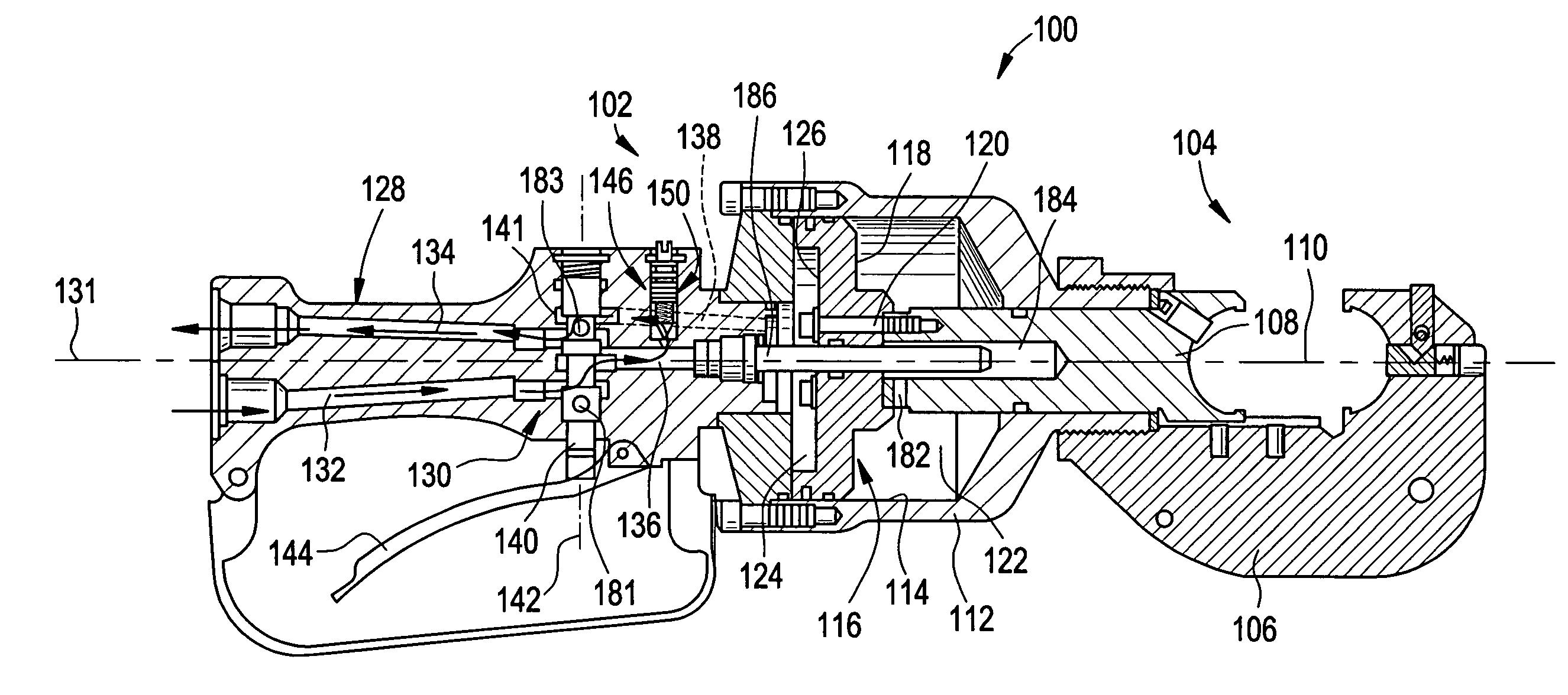
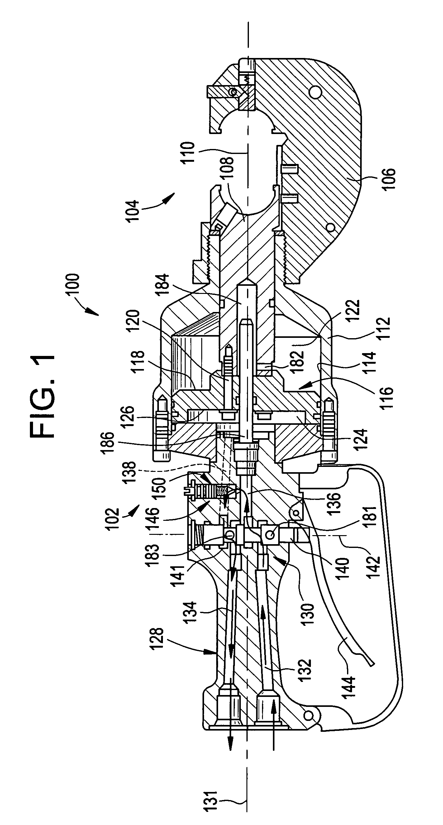
[0042]A first embodiment of the invention in which a crimping tool 100 is shown to have a novel control mechanism 102, which incorporates features of the invention, is illustrated in FIGS. 1–8 with reference numerals being in the one hundreds. A second embodiment of the invention in which a utility pruner tool 300 is shown to have a novel control mechanism 302, which incorporates features of the invention, is illustrated in FIGS. 9–16 with reference numerals being in the three hundreds. Like reference numerals in the first and second embodiments denote like elements.

Crimping Tool 100 Having The Novel Control mechanism 102

[004...


PUM


Abstract

A mechanism is provided for use with a hydraulic control mechanism of a hydraulic tool. The hydraulic control mechanism is attached to the hydraulic tool to provide a desired hydraulically powered function. The mechanism allows the hydraulic control mechanism to be used with either a constant volume hydraulic system or a constant pressure hydraulic system. The mechanism provides a valve chamber and a valve member positioned within the valve chamber. The valve chamber communicates with both a central passageway and a cross passageway of the hydraulic control mechanism. The valve chamber defines a valve seat proximate to one of the central and cross passageways. The valve member is displaceable within the valve chamber and is configured such that, depending on the position of the valve member within the valve chamber, the hydraulic control mechanism can be used with either a constant volume hydraulic system or a constant pressure hydraulic system.

Description

CROSS-REFERENCE[0001]This patent application claims the benefit of domestic priority of U.S. Provisional Application Ser. No. 60 / 490,160, filed Jul. 25, 2003, and entitled “Mechanism For Switching Between Closed Center And Open Center Hydraulic Systems”.BACKGROUND OF THE INVENTION[0002]This invention is directed generally to a mechanism for operating a hydraulic tool. More particularly, the present invention is directed to a mechanism employing a novel adjustment assembly for a hydraulic tool which allows the tool to be used with either a constant pressure hydraulic fluid system or a constant volume hydraulic fluid system without requiring disassembly or replacement of any parts in the tool.[0003]Hydraulic tools generally operate using one of two basic types of hydraulic systems. The hydraulic systems which are used to operate such tools include the constant volume system and the constant pressure system.[0004]In the constant volume system, the hydraulic fluid, such as oil, must be ...

Claims


Application Information

Patent Timeline
Patent Type & Authority Patents(United States)
IPC IPC(8): F15B11/08B25B27/10F15B13/00F15B21/08
CPCB25B27/10F15B11/08F15B21/082F15B2211/3116F15B2013/006F15B2211/3111
Inventor HARWATH, JULIEDIEKMANN, ORVILLE
Owner GREENLEE TEXTRON
Features
  • R&D
  • Intellectual Property
  • Life Sciences
  • Materials
  • Tech Scout
  • Unparalleled Data Quality
  • Higher Quality Content
  • 60% Fewer Hallucinations
Learn More