Process for the injection of an electric motor rotor

a technology of electric motors and rotors, which is applied in the manufacture of stator/rotor bodies, cage rotors, rotors, etc., can solve the problems of increasing the production cost of rotors, affecting the electromagnetic efficiency of rotors, and reducing productivity, so as to reduce the machining operation

Inactive Publication Date: 2006-01-31
EMBRACO IND DE COMPRESSORES E SOLUCOES EM REFRIGERACAO LTDA
View PDF6 Cites 16 Cited by
  • Summary
  • Abstract
  • Description
  • Claims
  • Application Information

AI Technical Summary

Benefits of technology

[0012]By reason of the above-mentioned problems related to the process for injecting rotors by centrifugation, it is the object of the present invention to provide a process for injecting these parts by centrifugation, which considerably reduces the machining operations to form the upper ring of the cage made of aluminum or other conductive material of the rotor, and eliminates the problem of deformation of the upper end lamination and consequently the penetration of aluminum between the upper laminations of the lamination stack.SUMMARY OF THE INVENTION
[0022]As it can be noted, the present process eliminates the harmful effects of the liquid metal contacting, at a high temperature, the exposed central portion of the upper end lamination, as well as the necessity of machining a large quantity of aluminum to form the central opening of the upper ring of the cage. The removal of the stamping pin causes the rupture of the upper plate of the metal, practically defining the central opening of the upper ring of the cage and only requiring, if needed, a slight machining (chamfering) for the finishing of the sharp edge to eliminate the barbs originated from the extraction of the stamping pin.

Problems solved by technology

These machining operations reduce the productivity and increase the production cost of the rotors, particularly the rotors of small dimensions with a large volume of production.
Furthermore, the penetration of aluminum between the laminations radially outwardly from the upper end region of the central axial bore 11 impairs the electromagnetic efficiency of the rotor.

Method used


Image

  • Process for the injection of an electric motor rotor
  • Process for the injection of an electric motor rotor
  • Process for the injection of an electric motor rotor

Examples


Embodiment Construction

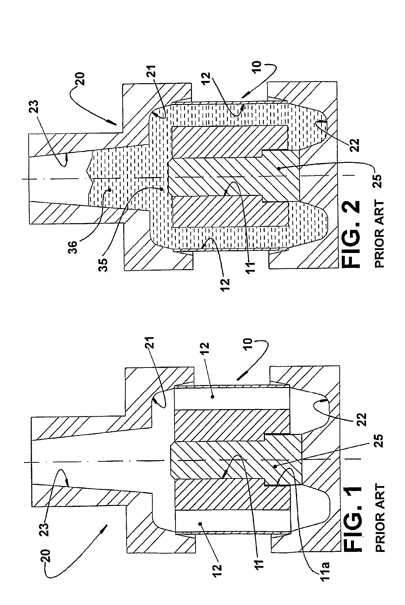
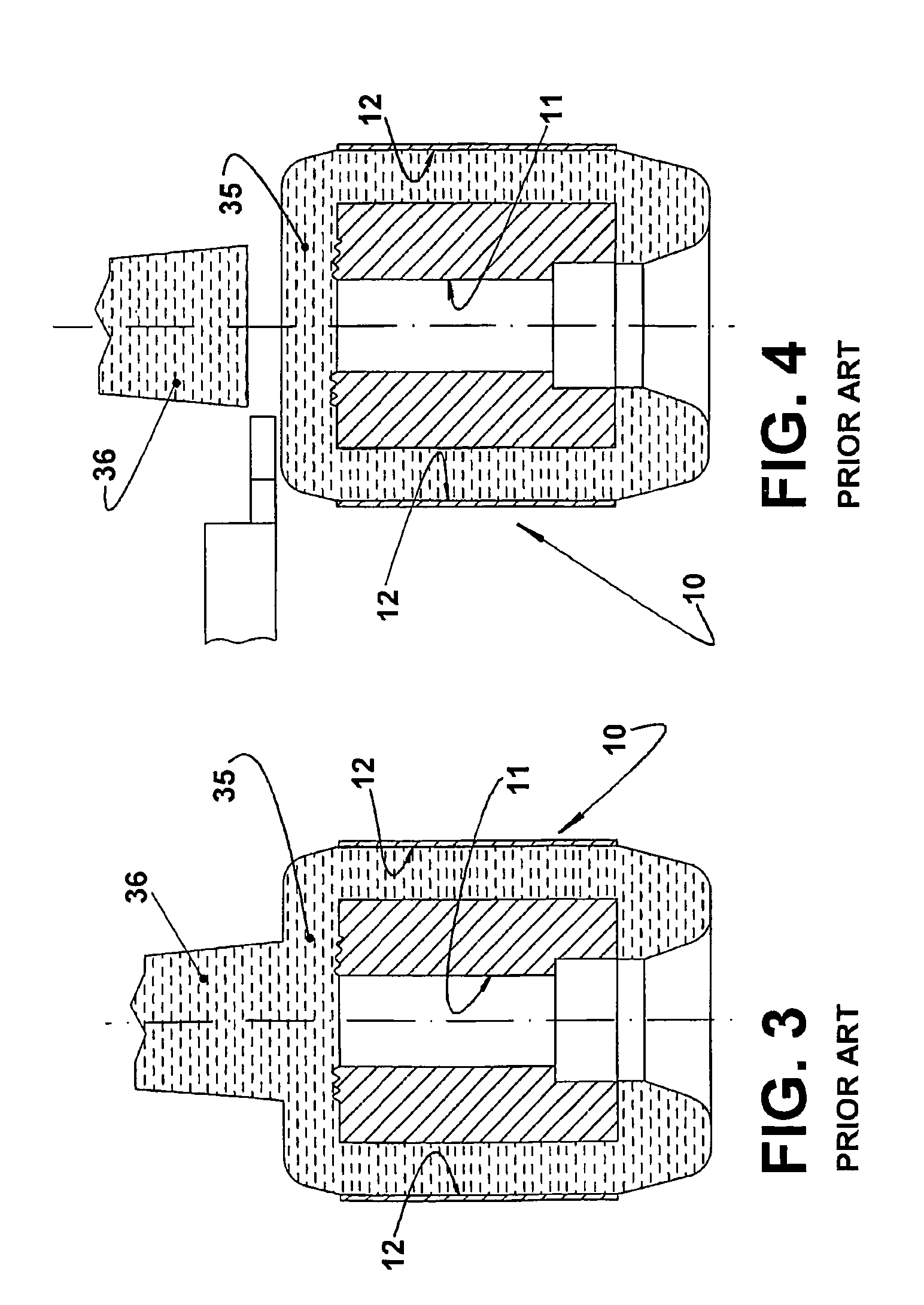
[0031]As already mentioned, in the process of injection by centrifugation shown in FIGS. 1–5, the injection of liquid aluminum (or other metal) into the upper cavity is directly made over the whole external annular surface of the upper end lamination of the lamination stack 10, producing deformations on said surface. Besides the problem above, the upper cavity 21 of the mold 20 is configured to provide the melting of a plate 35, incorporating an upper axial projection 36 defined inside the inlet channel 23, and which is partially used to compensate the contraction of the aluminum during the solidification.

[0032]This solution requires the machining operations schematically illustrated in FIGS. 4–5.

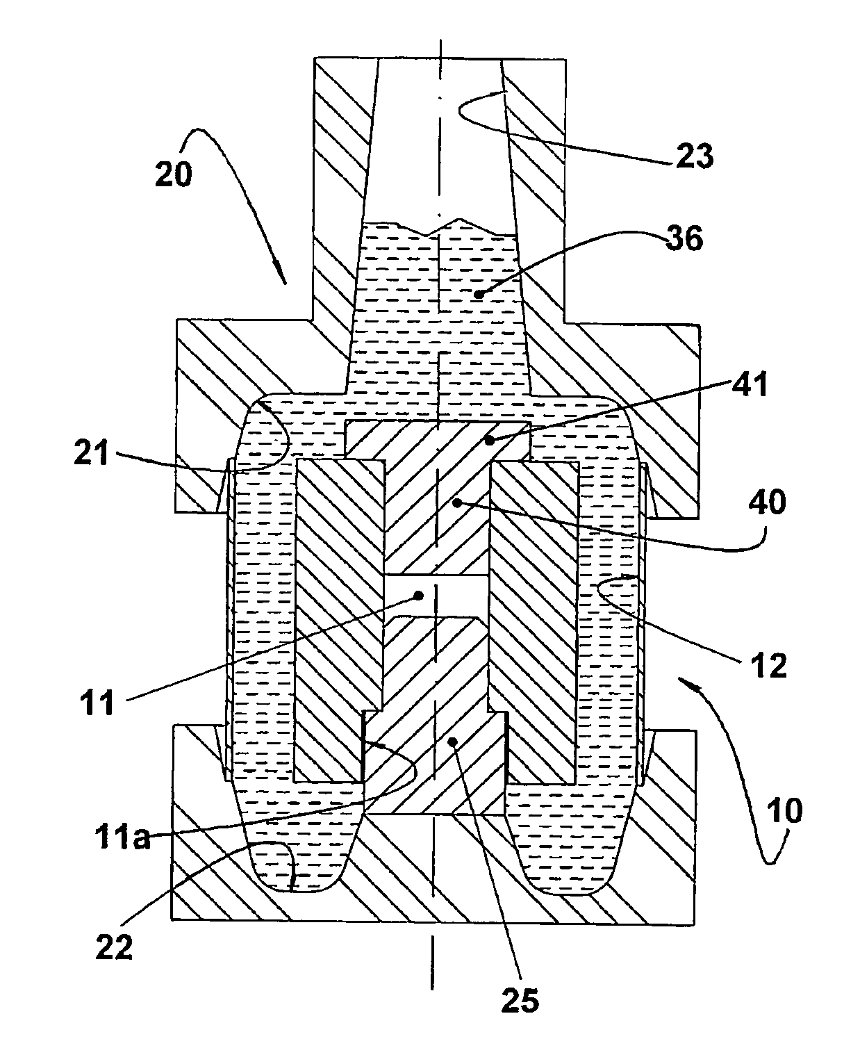
[0033]According to the process of the present invention, the lamination stack 10 has the lower end widening 11a of the central axial bore 11 filled with a respective core 25, which is fitted inside part of the extension of the central axial bore 11 of the lamination stack 10.

[0034]In the up...


PUM

PropertyMeasurementUnit
temperatureaaaaaaaaaa
melting temperatureaaaaaaaaaa
volumeaaaaaaaaaa

Abstract

A process for the injection of an electric motor rotor, said rotor comprising: a lamination stack (10) having a central axial bore (11) and a plurality of axial channels (12); and a cage (30) of aluminum, which is formed by an upper end ring (31) and a lower end ring (32), which are interconnected by a plurality of bars (33) molten in the axial channels (12). The process comprises the steps of: mounting, at the upper end portion of the central axial bore (11), a stamping pin (40), which has a widened head (41) seated against the upper end lamination of the lamination stack (10); heating the lamination stack, as well as an upper cavity (21) and a lower cavity (22) of a mold (20); positioning the lamination stack (10) inside the mold (20); rotating the mold (20) and pouring the aluminum into the inside thereof through the inlet channel (23); removing, from the mold (20), the rotor (R) with the cage (30) already formed and comprising an upper plate (35) that covers the stamping pin (40); and axially extracting the stamping pin (40) in order to break, centrally, the upper plate (35), transforming it in the upper ring (31) of the cage (30).

Description

CROSS-REFERENCE TO RELATED APPLICATION[0001]This application is a 371 of PCT / BR02 / 00192 filed on Dec. 20, 2002FIELD OF THE INVENTION[0002]The present invention refers to a process for providing the injection, by centrifugation, of the cage made of aluminum, or other adequate metal, into the stack of steel laminations of the rotor of an electric motor, particularly the rotor of small electric motors, such as those used in the hermetic compressors of small refrigeration systems.BACKGROUND OF THE INVENTION[0003]It is already known from the prior art the injection, by centrifugation, of the aluminum cages in rotors, which are formed by a stack of overlapped identical annular steel laminations provided with openings that are longitudinally aligned with the openings of other laminations of the stack, in order to define a plurality of axial channels interconnecting the external faces of the end laminations of the stack and which are angularly spaced from each other along a circular alignme...

Claims


Application Information

Patent Timeline
Patent Type & Authority Patents(United States)
IPC IPC(8): B22D19/00H02K15/02B22D13/04B22D29/00H02K15/00
CPCB22D13/04H02K15/0012B22D29/001B22D19/0054B22D19/00B22D29/00H02K15/00
Inventor RAMIREZ, RIVIO ARTUROKRZEMINSKI, EDISONDROZDEK, CLAUDIO ANTONIO
Owner EMBRACO IND DE COMPRESSORES E SOLUCOES EM REFRIGERACAO LTDA
Why Eureka
Try Eureka