
Printing method, print unit, program for the same, and storage medium for the same

a printing method and print unit technology, applied in the direction of printing, electrical apparatus, visual presentation using printers, etc., can solve the problems of affecting image quality, deterioration of image quality, and inability to meet the needs of printing, so as to reduce the sense of noise in the image further, the effect of high spatial frequency characteristic and high image quality

Inactive Publication Date: 2006-01-31
CANON KK
View PDF7 Cites 20 Cited by
  • Summary
  • Abstract
  • Description
  • Claims
  • Application Information

AI Technical Summary

Benefits of technology

[0027]This invention can provide a printing method, a print apparatus, a program, and a storage medium that can prevent a pattern arising from the periodicity of the dot arrangements from appearing in the image as noises such as a streak and print a high-quality image in the case where a plurality of different dot arrangements each displaying the same level of gradation of the input image data are used repeatedly in a unit of predetermined number of the dot arrangements.
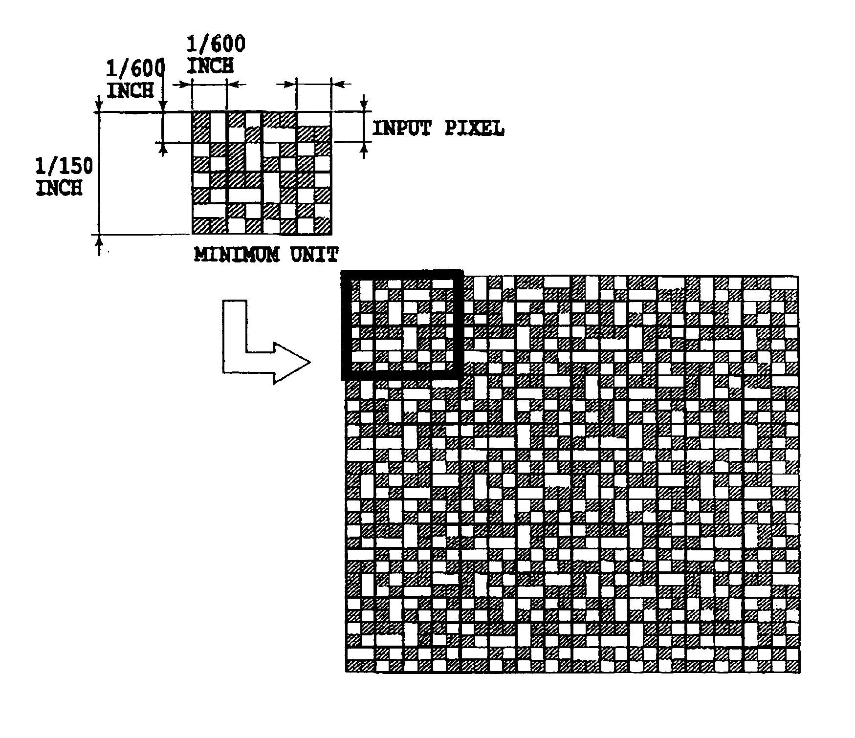
[0041]In this invention, a matrix of A×B is created by combining a plurality of different dot arrangements, each displaying the same level of gradation of the input image in the raster direction and in the column direction (the matrix is paved with plural dot arrangements), and this matrix is allocated to the input image data as a minimum unit. By this arrangement, the periodicity of the dot patterns in the image yields only a high spatial frequency characteristic, thus reducing the sense of noise in the image further; therefore, the image quality can be increased. Human vision has a highest sensitivity of perception for a period of approximately 200 μm when the observation distance is about 30 cm, and when the period goes to a higher spatial frequency or to a lower spatial frequency, the sensitivity of perception becomes dull. Moreover, when the dot size is the diameter of approximately 30 mm, the dimensions of each dot arrangement that corresponds to one input image data (one input pixel) is set to 1 / 600 inch square, and as a matrix, a matrix of 4×4 created by combining four dot arrangements in the raster direction and in the column direction is used, whereby the repetition period of the matrix can be set to a high spatial frequency, to which the human visual characteristic has dull sensitivity.
[0043]Furthermore, as the matrix, a matrix such that A kinds of dot arrangements are arranged in each raster, a repetition sequence of the dot patterns in the raster direction is the same for every raster, and a starting position of the repetition sequence is different in each raster is used, whereby the periodicity of the patterns can be controlled to exist in a higher frequency, and consequently the sense of noise caused by a streak, etc., in the image can be reduced further.
[0045]Moreover, by using a matrix of 4×4 created by combining four dot arrangements in the raster direction and in the column direction, setting the dimensions of each dot arrangement to 1 / 600 inch square, and setting the diameter of the dot formed on the printing medium to 30 μm, the sense of noise caused by a streak, etc., appearing in the image can be reduced, so that a higher-quality image can be printed. Moreover, an arrangement sequence of a plurality of dot patterns in the matrix can be set, for example, in such a way that the repetition sequence of the dot patterns in the raster direction is the same for every raster and a starting position of the repetition sequence is different in each raster. In this case, control for making the periodicity of the dot patterns in the image yield a high spatial frequency characteristic becomes easier to carry out, thus reducing the sense of noise in the image further; therefore the image quality can be increased.

Problems solved by technology

For example, due to a constraint in manufacture of the multi-nozzle head, there is inevitably a limit in the density of a nozzle array on a single line.
Moreover, in the case where such a head as shown in FIG. 16A is used, since even-number rasters and odd-number rasters that are to be arranged alternately in the y-direction (sub scanning direction) are printed by different ejection opening arrays, impact positions of dots formed by one ejection opening array are displaced slightly from those formed by other array and hence there may occur deterioration in the image quality.
For example, if a convex deformation has occurred therein between the ejection opening array taking part in printing of the odd-number rasters (odd-number nozzle array) and the ejection opening array taking part in even-number rasters (even-number nozzle array), the ink is ejected from each ejection opening array in a different direction, i.e., in the shape of a character “Λ.” Displacement of ink impact position between rasters arising from such a phenomenon causes detrimental effects on the image quality, although the amount is very little, and the deterioration becomes significant in high-resolution images obtained by a binarization method, such as the error diffusion method.
However, dot patterns affect the image quality largely, and in the case where plural kinds of patterns of dot arrangements each displaying the same level of gradation are arranged at random in the main scanning direction, there is the possibility that noises such as roughness and a sense of granularity may occur in the image.
In the case where the area of arrangement of dot patterns in the main scanning direction cannot be secured wide enough because of a constraint of memory capacity, a period of the area appears in the image, gives a sense of noise, and leads to deterioration in the image quality.

Method used


Image

  • Printing method, print unit, program for the same, and storage medium for the same
  • Printing method, print unit, program for the same, and storage medium for the same
  • Printing method, print unit, program for the same, and storage medium for the same

Examples


second embodiment

[0154]FIG. 13 is an explanatory diagram for an example of the composition of the matrix in this invention.

[0155]In this embodiment, as in the case of the embodiment described above, a matrix of (4×4) in which four dot patterns are arranged both in the main scanning direction (a horizontal direction in the figure) and the sub scanning direction (vertical direction in the figure) is created as a minimum unit, which is used repeatedly in the main scanning direction and in the sub scanning direction to conduct printing. Note that in this embodiment, as shown in FIG. 13, different dot patterns each displaying the same level of gradation are arranged in a different order for each raster along the main scanning direction in its minimum-unit matrix (a set of dot patterns).

[0156]FIG. 13 shows an example of the composition of the matrix for a level of gradation of “level 2.” In the matrix, four dot patterns A, B, C, and D each for “level 2” are arranged on each of the same raster, wherein an ...

third embodiment

[0157]FIG. 14 is an explanatory diagram of an example of the composition of the matrix in this invention.

[0158]In this embodiment, as in the case of the embodiment described above, a matrix of dot patterns (4×4) in which four dot patterns are arranged in the main scanning direction (horizontal direction in the figure) and in the sub scanning direction (vertical direction in the figure) is created as a minimum unit, which is used repeatedly in the main scanning direction and in the sub scanning direction to conduct printing. Note that in this embodiment, as shown in FIG. 14, different dot patterns with the same level of gradation are arrayed in a predetermined sequence in each raster along the main scanning direction in the minimum-unit matrix (a set of dot patterns). The arrangement sequence of dot patterns in this example is set in such a way that repetition sequences of the dot patterns in the raster direction are set identical for each raster and a starting position of the repeti...


PUM


Abstract

The invention prevents a pattern arising from periodicity of dot arrangements from appearing as noise, such as a streak, when a plurality of different dot arrangements are used repeatedly in a unit of a predetermined number of the dot arrangements for the same level of gradation of input image data, and thereby makes it possible to print a high-quality image. To this end, when input image data quantized to one of multivalued levels of gradation is allocated to a dot arrangement of M×N, a matrix of A×B created by combining a plurality of different dot arrangements each displaying the same level of gradation of the input image data in a raster direction and in a column direction is used as a minimum unit, and the dot arrangement of this matrix is allocated to the input image data.

Description

[0001]This application claims priority from Japanese Patent Application No. 2002-255904 filed Aug. 30, 2002, which is incorporated hereinto by reference.BACKGROUND OF THE INVENTION[0002]1. Field of the Invention[0003]This invention relates to a printing method, a print apparatus, a program, and a storage medium, and more specifically, to those that are applied to position adjustment of ink dot formation in an inkjet printing system with a preferable result. In addition, this invention is applicable to a copier, a facsimile having a communication system, equipment having a printing portion, such as a word processor, and further an industrial printing system that is combined with any of various kinds of processing devices in a sophisticated manner as well as general print units.[0004]2. Description of the Related Art[0005]A so-called serial scan type image printing system that executes a printing operation with a printing head that is a major constituent of a printing portion being sc...

Claims


Application Information

Patent Timeline
Patent Type & Authority Patents(United States)
IPC IPC(8): B41J2/145B41J2/15B41J2/01B41J2/205G06K15/02H04N1/405
CPCB41J2/2054H04N1/4055G06K15/02
Inventor MARU, AKIKOTAJIKA, HIROSHIKONNO, YUJIIDE, DAISAKUYAZAWA, TAKESHIMASUYAMA, ATSUHIKO
Owner CANON KK
Learn More