Digital voltage regulator for DC/DC converters

a digital voltage regulator and converter technology, applied in the field of power conversion, can solve the problem that the usefulness of the feedback mechanism controlling the switch is fundamentally limited, and achieve the effect of reducing the delay in the feedback path

Inactive Publication Date: 2006-01-31
KIAWE FOREST
View PDF3 Cites 52 Cited by
  • Summary
  • Abstract
  • Description
  • Claims
  • Application Information

AI Technical Summary

Benefits of technology

[0016]When these insights are combined in a duty cycle quantization mechanism for determining, from an estimated target duty cycle, a first set of one or more quantized ON time / OFF time pairs for regulating the output voltage, and in a novel output-voltage-error-driven selector mechanism for determining the turn ON and turn OFF times of the switching device by choosing, cycle by cycle, from a second set of two or more quantized ON time / OFF time pairs, derived from the first set, the ripple induced by quantization as well as the delay in the feedback path are reduced. To illustrate the latter point, the choosing of ON time / OFF time pairs, instead of ON times, means that the choice can be broken into two choices: ON time and OFF time; and that feedback measured during the ON time AND during the OFF time may be applied virtually instantaneously to regulate the output voltage.

Problems solved by technology

The novelty of the selector mechanism follows from the insight that in a temporally quantized switching environment, the feedback mechanism controlling the switch is fundamentally limited in the amount of useful information it can provide at each cycling of the switch.

Method used


Image

  • Digital voltage regulator for DC/DC converters
  • Digital voltage regulator for DC/DC converters
  • Digital voltage regulator for DC/DC converters

Examples


Embodiment Construction

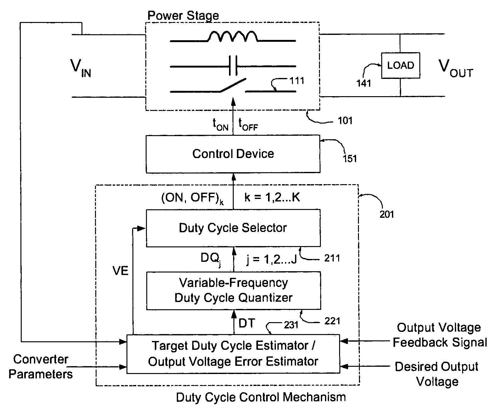
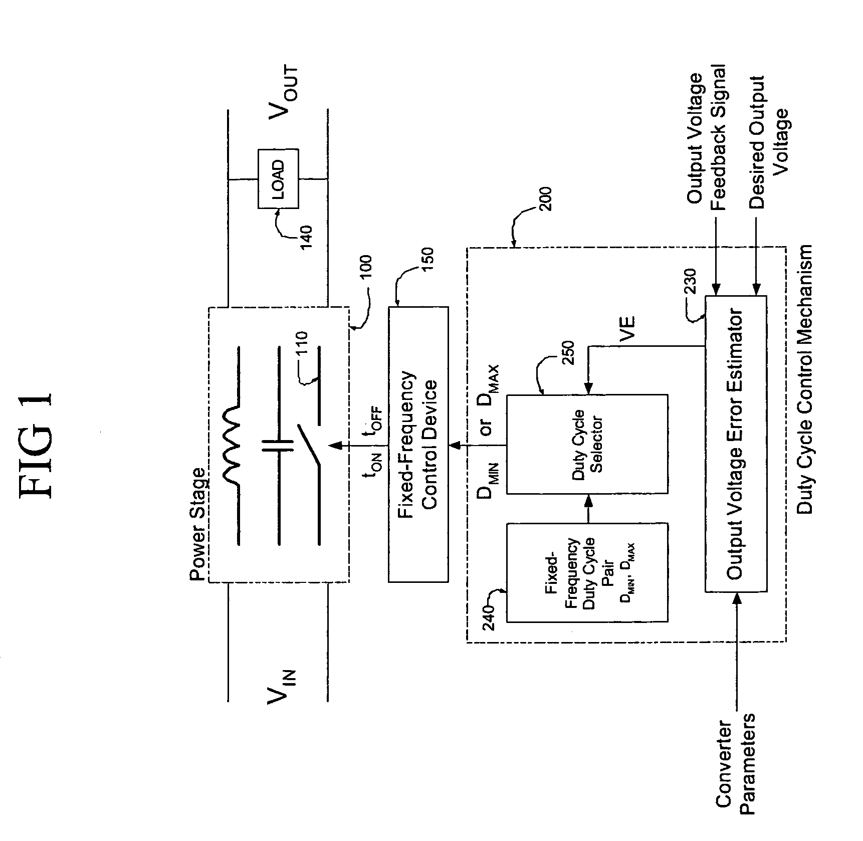
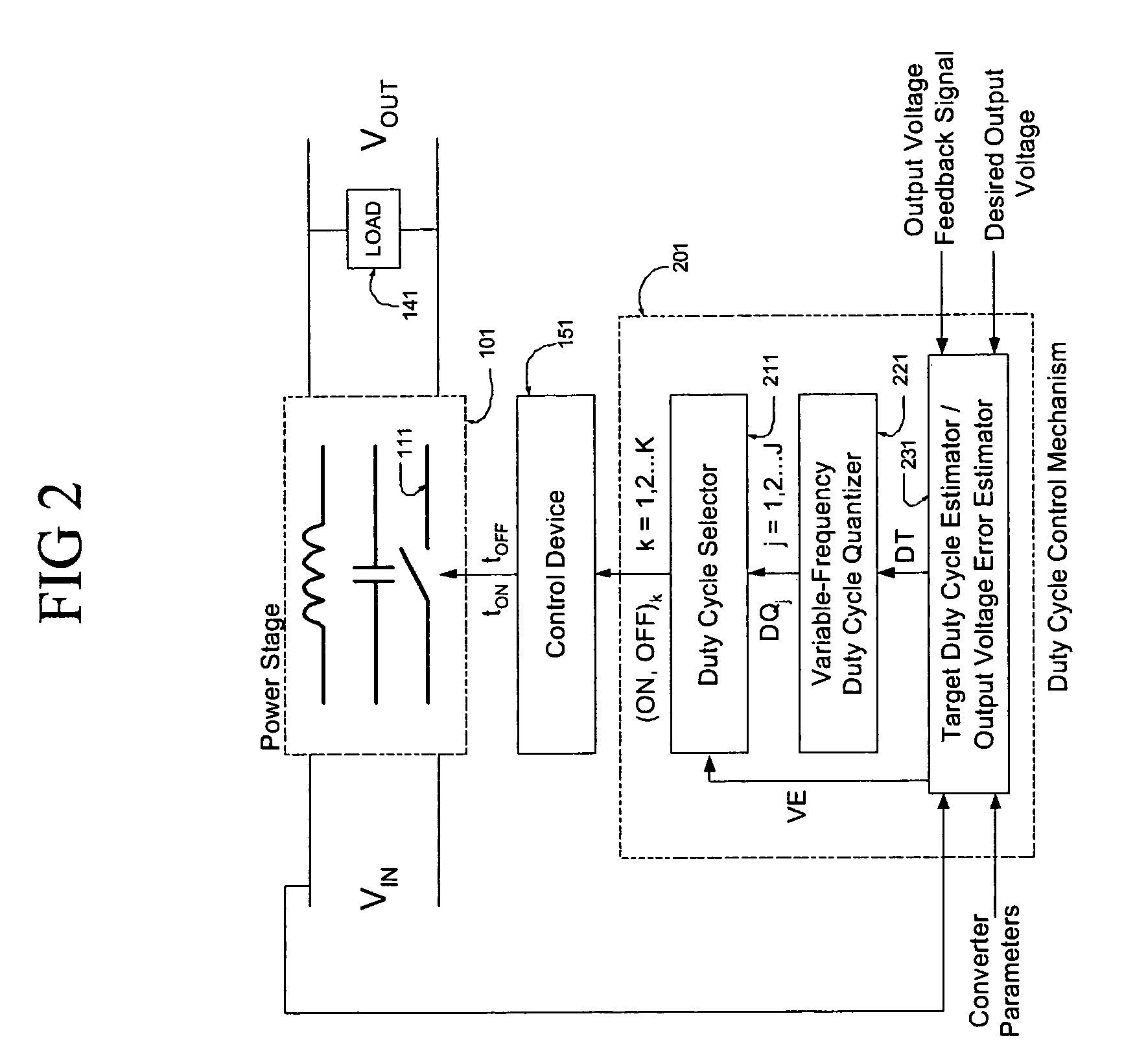
[0039]A broad class of switched-mode DC / DC power converters exists with the property that the ratio of the average output voltage to the input voltage is determined by the average duty cycle of a controllable switching device within the power conversion stage of the converter. Examples include buck, boost, inverting buck-boost, forward, and flyback converters, operated in the continuous conduction mode (CCM). Where the load on the power converter varies dynamically, or there is a requirement to track changes in load with minimal output voltage error, regulation of these converters is accomplished by continually estimating the output voltage error (the output voltage error being the difference between the uncorrupted output voltage and the desired output voltage) and continually adjusting the duty cycle of the switching device to compensate for changes in load conditions manifest in output voltage error estimates. In this case, the act of regulation consists of controlling, cycle by ...


PUM


Abstract

A digitally-controlled, DC/DC converter includes at least one switched-mode power stage for the purpose of converting an input voltage (Vin) into an output voltage (Vout); the power stage including at least one controllable switching device, which is turned ON and OFF by a control device with temporal resolution Δt. The converter further includes a duty cycle control mechanism for controlling the duty cycle of the controllable switching device, the duty cycle control mechanism including a mechanism for estimating the output voltage error; a mechanism for estimating the target duty cycle; a duty cycle quantization mechanism for determining, for a target duty cycle estimate, a first set of quantized ON time/OFF time pairs suitable for controlling the switching device; and a selector mechanism for determining the turn ON and turn OFF times of said controllable switching device by choosing, cycle by cycle, an ON time/OFF time pair from a second set of quantized ON time/OFF time pairs, derived from said first set, choosing in such a manner that the amplitude of the output voltage error is continually minimized.

Description

CROSS-REFERENCE TO RELATED APPLICATIONS[0001]Not ApplicableSTATEMENT REGARDING FEDERALLY SPONSORED RESEARCH OR DEVELOPMENT[0002]Not ApplicableBACKGROUND OF THE INVENTION[0003]The invention pertains generally to the field of power conversion, and more particularly to digitally-controlled switched-mode DC / DC converters.[0004]A broad class of switched-mode DC / DC power converters exists with the property that the ratio of the average output voltage to the input voltage is determined by the average duty cycle of a controllable switching device within the power conversion stage of the converter. Examples include buck, boost, inverting buck-boost, forward, and flyback converters, operated in the continuous conduction mode (CCM). Where the load on the power converter varies dynamically, or there is a requirement to track changes in load with minimal output voltage error, regulation of these converters is accomplished by continually estimating the output voltage error (the output voltage err...

Claims


Application Information

Patent Timeline
Patent Type & Authority Patents(United States)
IPC IPC(8): G05F1/46
CPCH02M3/157
Inventor KING, PAUL FREDERIC
Owner KIAWE FOREST
Why Eureka
Try Eureka