System for controlling video and motion picture cameras

a technology for video and motion pictures, applied in the field of video and motion picture cameras, can solve the problems of limiting the interface from instantaneously panning to a new destination, and the limitations of mechanical systems,

Inactive Publication Date: 2006-01-31
FUJIFILM BUSINESS INNOVATION CORP
View PDF16 Cites 75 Cited by
  • Summary
  • Abstract
  • Description
  • Claims
  • Application Information

AI Technical Summary

Benefits of technology

[0018]Each method and embodiment of the present invention provides a...

Problems solved by technology

However, such systems are constrained by the limitations of the mechanical systems that orient them.
Even professional systems have on...

Method used


Image

  • System for controlling video and motion picture cameras
  • System for controlling video and motion picture cameras
  • System for controlling video and motion picture cameras

Examples


Embodiment Construction

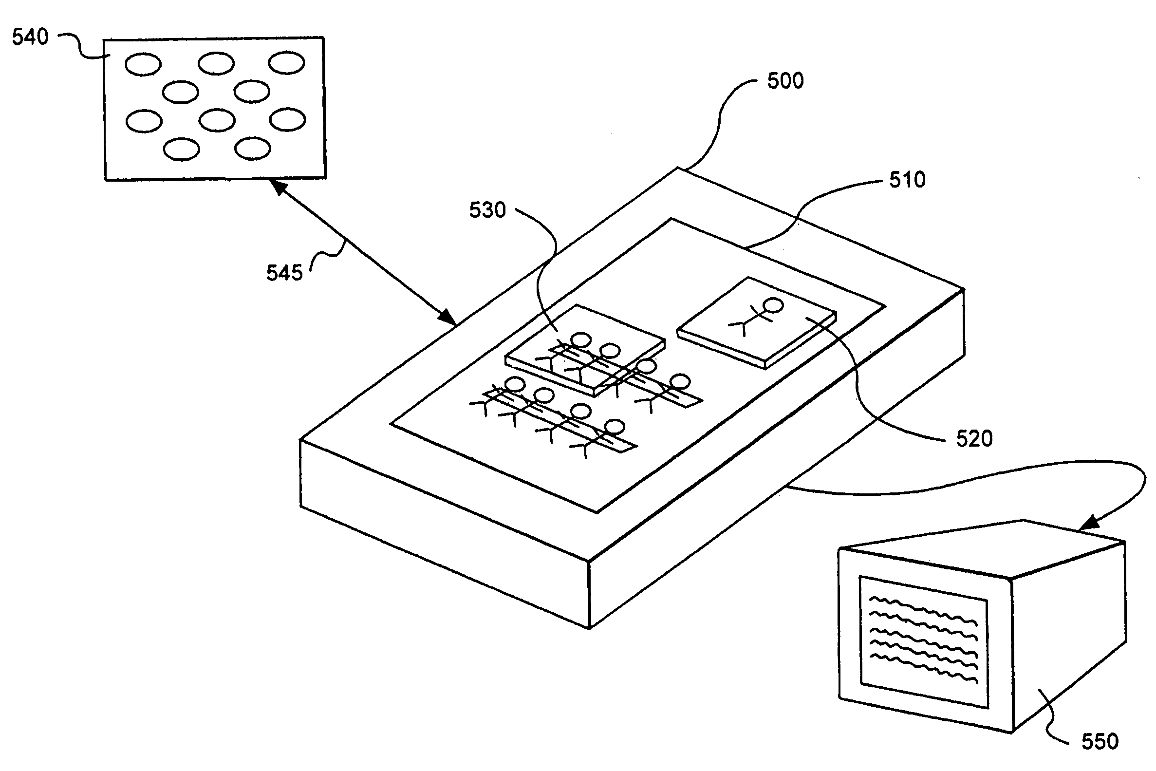
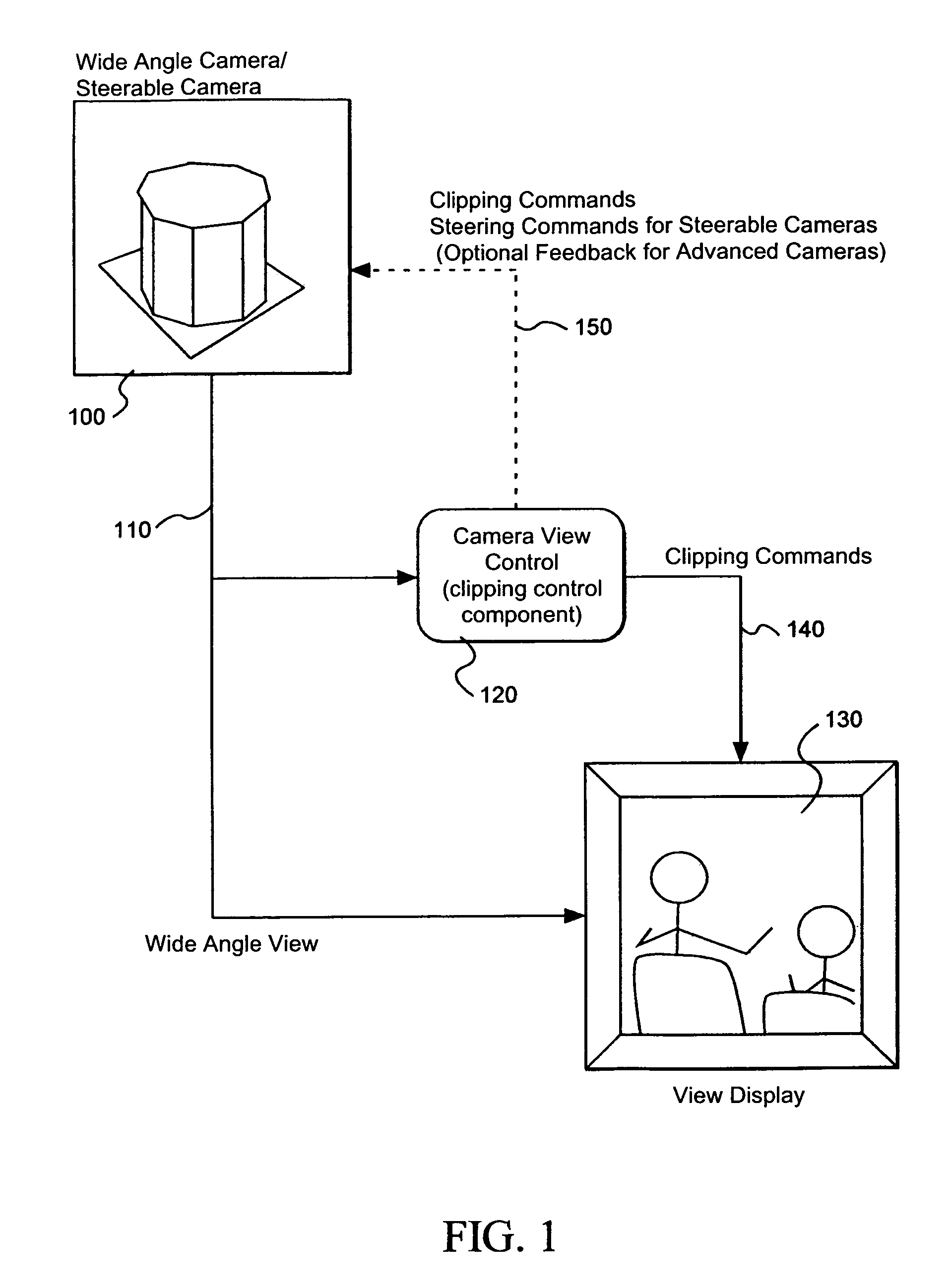
[0035]Referring now to the drawings, wherein like reference numerals designate identical or corresponding parts, and more particularly to FIG. 1 thereof, there is illustrated a flow of image and control data through a system that is shared by several embodiments of the present invention. The system includes a camera 100. The camera 100 is illustrated as a camera array, and may also be embodied as any camera or image capture device, such as a simple digital or analog camera, a camera array, wide angle camera, and a steerable camera, for example.

[0036]The camera 100 provides a wide-angle camera view of a scene to support an electronic clipping process. A camera data stream 110 is split and directed simultaneously to a clipping control component 120 (also referred to as the camera view control 120) and a display view 130 (e.g., videoconference image, meeting capture recording, display device, etc).

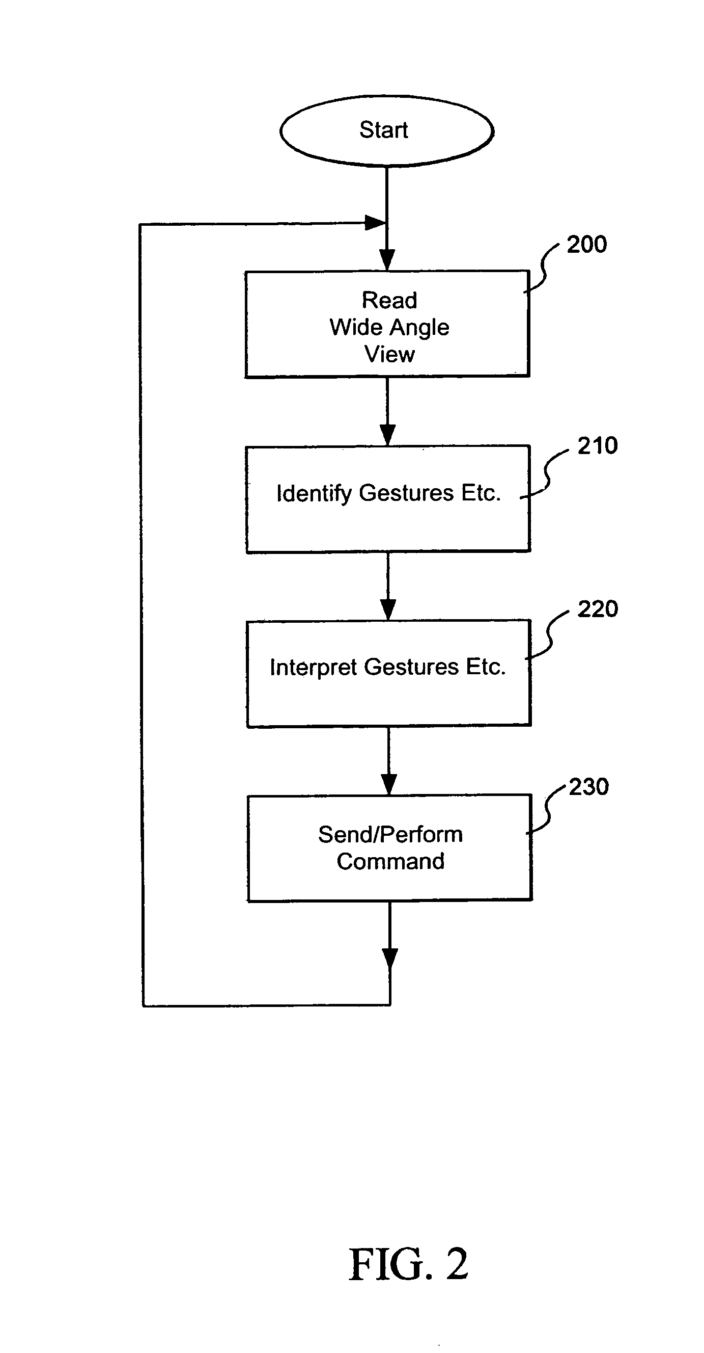
[0037]In one embodiment, simple user actions are captured by the camera view control 120 ...


PUM


Abstract

Inputs drawn on a control surface or inputs retrieved based on tokens or other objects placed on a control surface are identified and a view of a camera, or a virtual view of a camera or camera array is directed toward a corresponding location in a scene based on the inputs. A panoramic or wide angle view of the scene is displayed on the control surface as a reference for user placement of tokens, drawings, or icons. Camera icons may also be displayed for directing views of specific cameras to specific views identified by any of drag and drop icons, tokens, or other inputs drawn on the control surface. Clipping commands, are sent to a display device along with the wide angle view which is then clipped to a view corresponding to the input and displayed on a display device, broadcasting mechanism, or provided to a recording device.

Description

COPYRIGHT NOTICE[0001]A portion of the disclosure of this patent document contains material which is subject to copyright protection. The copyright owner has no objection to the facsimile reproduction by anyone of the patent document or the patent disclosure, as it appears in the Patent and Trademark Office patent file or records, but otherwise reserves all copyright rights whatsoever.BACKGROUND OF THE INVENTION[0002]1. Field of Invention[0003]This invention relates to a method and apparatus for control of one or more cameras, including motion picture cameras. The invention is also related to the control of a video camera array. The invention is more particularly related to controlling parameters of a shot of a still or video camera, particularly a pan angle and zoom of the camera being controlled. The invention is also related to interfaces for implementing control of the above and other camera parameters, including pen-based, illumination, and gesture based control interfaces.[000...

Claims


Application Information

Patent Timeline
IPC IPC(8): H04N5/232G06T1/00G06F3/00G06F3/038G06F3/042G06T11/80H04N5/225H04N7/15
CPCG06F3/0386H04N5/232G06F3/04883H04N23/61H04N23/631H04N23/695
Inventor FOOTE, JONATHANNELSON, LESDOHERTY, JOHN J.
Owner FUJIFILM BUSINESS INNOVATION CORP
Why Eureka
Try Eureka