Iris identifying apparatus
a technology of identifying apparatus and iris, which is applied in the field of identifying apparatus, can solve problems such as difficulty for users, and achieve the effect of convenient handling
- Summary
- Abstract
- Description
- Claims
- Application Information
AI Technical Summary
Benefits of technology
Problems solved by technology
Method used
Image
Examples
first embodiment
[0025
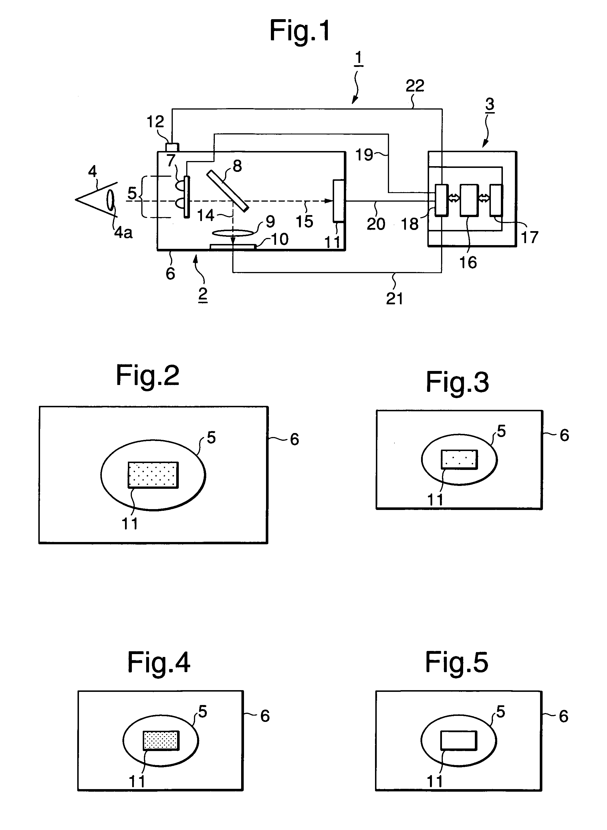
[0026]FIG. 1 is a block diagram of an iris identifying apparatus 1 according to the first embodiment of the invention, FIG. 2 is a front view of an image pickup unit, FIG. 3 is an explanatory diagram showing the flickering of guide lights, FIG. 4 is an explanatory diagram showing the light-ON state of guide lights, and FIG. 5 is an explanatory diagram showing the light-OFF state of guide lights. The iris identifying apparatus 1, which is of a handheld type, comprises an image pickup unit 2 and an identifying unit 3. A target person who undergoes image sensing holds the image pickup unit 2 by one hand and looks into it in one eye.
[0027]The image pickup unit 2 has a view window 5 formed in one end face of a case 6, which houses an infrared illumination 7, a hot mirror 8, a lens 9, an image pickup device 10 and guide lights 11 and has an operation switch 12 provided on the top surface. The view window 5 has a size (about φ30 mm) large enough for one eye 4 of the target person to l...
second embodiment
[0046
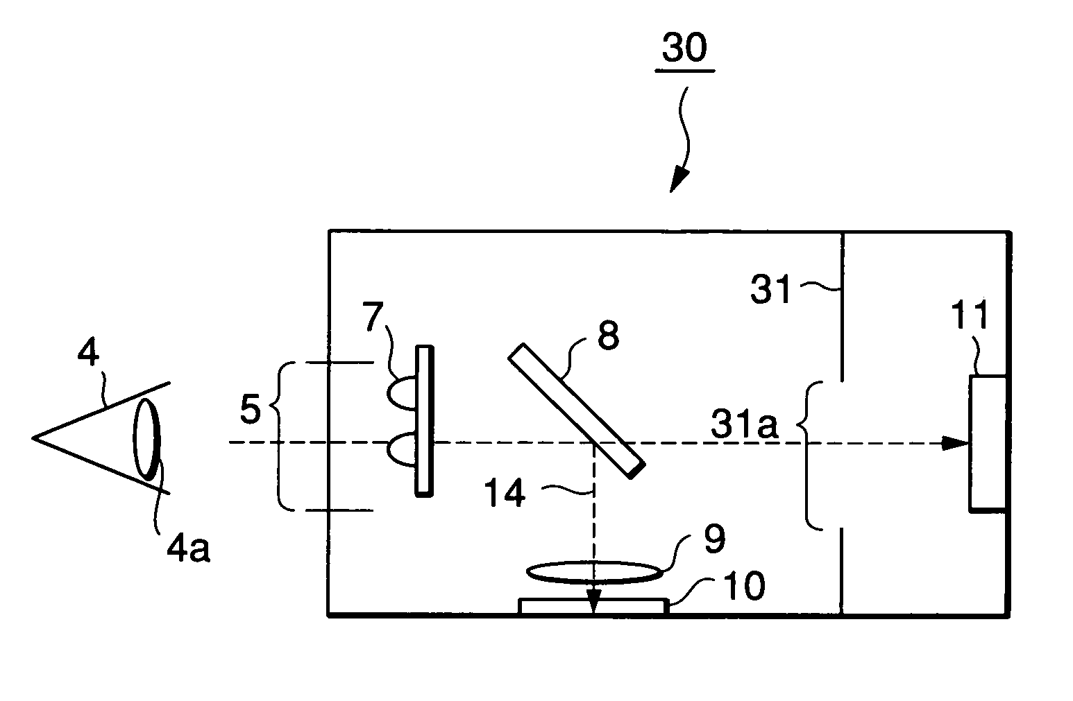
[0047]FIG. 7 is a block diagram of an image pickup unit according to the second embodiment of the invention, and FIG. 8 shows a guide frame and guide lights which are seen through the view window of the image pickup unit.
[0048]The iris identifying apparatus of the second embodiment differs significantly from the iris identifying apparatus of the first embodiment in that an image pickup unit 30 has a guide frame body 31, located between the guide lights 11 and the hot mirror 8, which has a guide frame 31a and guides the center position of the eye 4 of a target person to the center of the image pickup field.
[0049]The diameter of the iris 4a is about 11 mm on average, so that when the image pickup device whose picked-up image has a resolution of about 640 pixels×480 pixels is used, the image pickup field becomes 32 mm×24 mm.
[0050]Further, the iris identifying apparatus has a capability of detecting the center position of the iris 4a (when the entire image of the iris 4a is not in ...
third embodiment
[0058
[0059]FIG. 10 is a front view of an image pickup unit according to the third embodiment of the invention and FIG. 11 is a front view of the image pickup unit shown in FIG. 10. The iris identifying apparatus of the third embodiment differs from the iris identifying apparatus of the second embodiment in the structure of an image pickup unit 40.
[0060]The image pickup unit 40 has infrared illuminations 7 and 7 arranged on the respective sides of the view window 5 at a distance S of about 40 mm between the two so that the infrared rays reflected at one of glasses 41 a target person is wearing are directed out of the image pickup field.
[0061]FIG. 12 is an explanatory diagram for explaining glass reflection at the position of infrared illumination. In FIG. 12, a distance A indicates the case where infrared illuminations 7a and 7a are arranged at the respective sides of the view window 5 at the distance S of about 40 mm set between both illuminations (i.e., where the infrared illuminat...
PUM
 Abstract
Description
Claims
Application Information
 - R&D
- Intellectual Property
- Life Sciences
- Materials
- Tech Scout
- Unparalleled Data Quality
- Higher Quality Content
- 60% Fewer Hallucinations
Browse by: Latest US Patents, China's latest patents, Technical Efficacy Thesaurus, Application Domain, Technology Topic, Popular Technical Reports.
© 2025 PatSnap. All rights reserved.Legal|Privacy policy|Modern Slavery Act Transparency Statement|Sitemap|About US| Contact US: help@patsnap.com


