
Lens barrel having cam-cylinder with cam-groove and varying wall thickness, lens barrel having guide-cylinder with varying wall thickness, and lens barrel having the cam-cylinder and the guide-cylinder

Inactive Publication Date: 2006-01-31
CANON KK
View PDF5 Cites 0 Cited by
  • Summary
  • Abstract
  • Description
  • Claims
  • Application Information

AI Technical Summary

Benefits of technology

[0023]Accordingly, it is an object of the present invention to provide a compact, lightweight lens-barrel that is durable against a large impact. A lens barrel according to the present invention includes a lens-holding cylinder which supports a lens and is provided with a cam-follower and a rectilinear key; a cam-cylinder having a cam-groove which engages with the cam-follower so as to apply a driving force to the lens-holding cylinder in the optical-axis direction; and a guide cylinder which is enclosed by the cam-cylinder and has a rectilinear guide opening that engages with the rectilinear key so as to guide the lens-holding cylinder in the optical-axis direction. The cam-cylinder has a first segment and a second segment, and the wall thickness of the first segment is greater than that of the second segment such that the first segment has a higher elevation than the second segment in the inner periphery of the cam-cylinder. The guide cylinder has a first portion and a second portion. The first portion corresponds to the first segment of the cam-cylinder, and the second portion corresponds to the second segment of the cam-cylinder. The wall thickness of the second portion is greater than that of the first portion such that the second portion has a higher elevation than the first portion on the outer periphery of the guide cylinder.

Problems solved by technology

More specifically, the front surface of the lens barrel, for example, was subjected to a large impact when the camera was dropped.
With such a structure, however, there are cases where a large impact may force the cam-follower, i.e. the pin 121a, to become wedged into the cam-groove 116c, causing the lens barrel to break.
These additives, however, cause problems and are not desirable due to the fact that they lower the reliability of the mold used for the fabrication of the lens barrel.

Method used


Image

  • Lens barrel having cam-cylinder with cam-groove and varying wall thickness, lens barrel having guide-cylinder with varying wall thickness, and lens barrel having the cam-cylinder and the guide-cylinder
  • Lens barrel having cam-cylinder with cam-groove and varying wall thickness, lens barrel having guide-cylinder with varying wall thickness, and lens barrel having the cam-cylinder and the guide-cylinder
  • Lens barrel having cam-cylinder with cam-groove and varying wall thickness, lens barrel having guide-cylinder with varying wall thickness, and lens barrel having the cam-cylinder and the guide-cylinder

Examples


Embodiment Construction

[0038]An embodiment of the present invention will now be described with reference to the drawings.

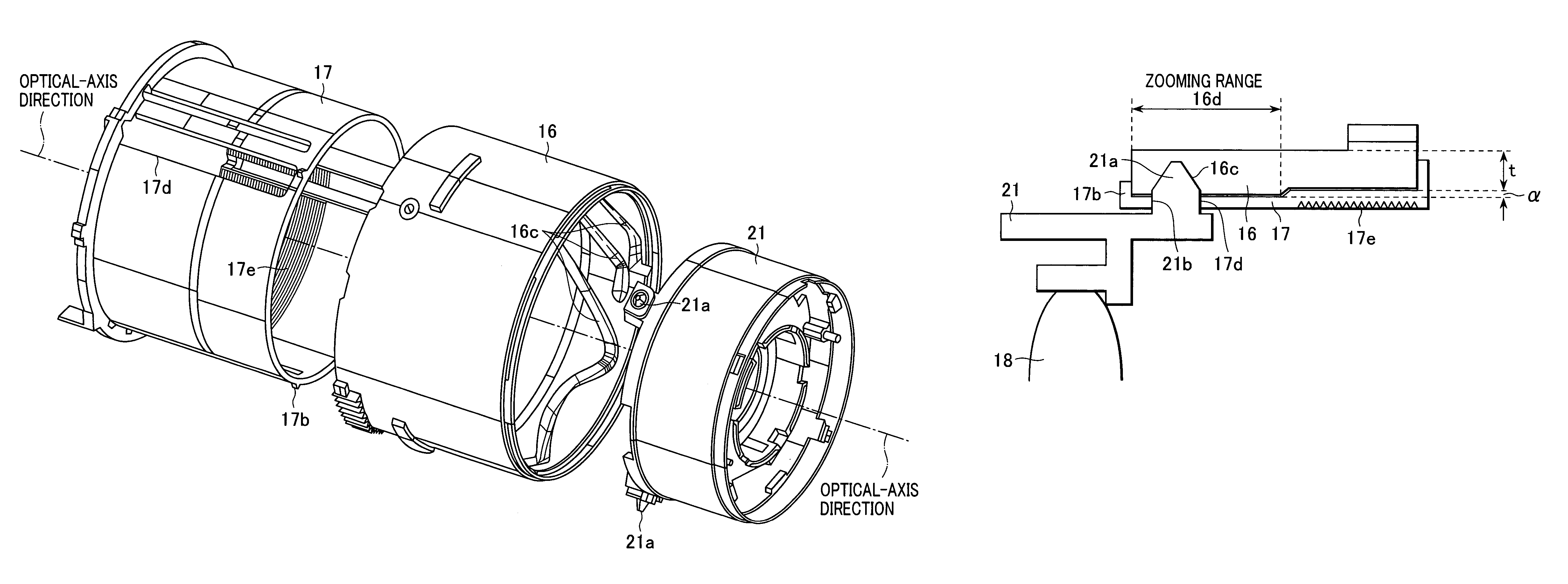
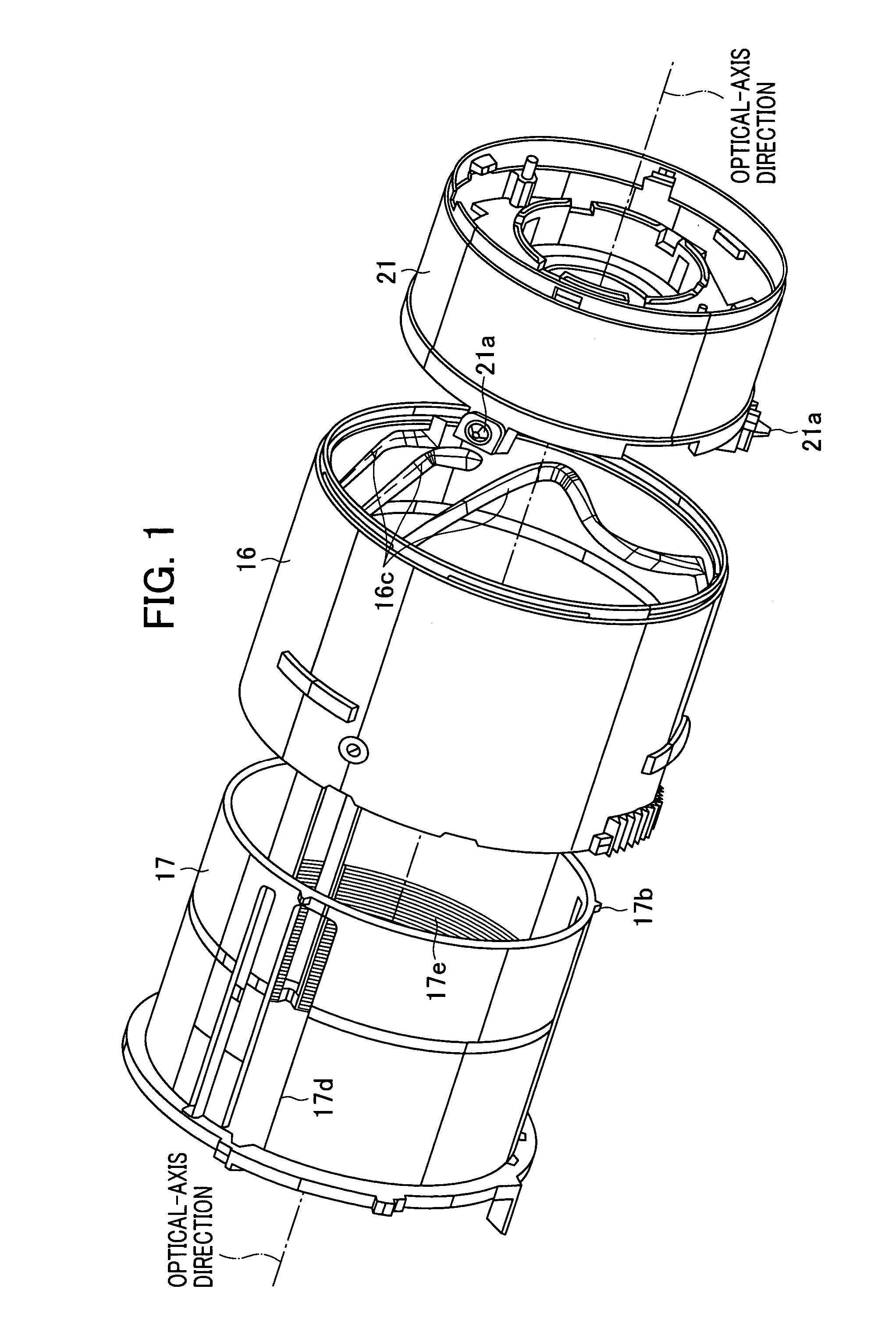
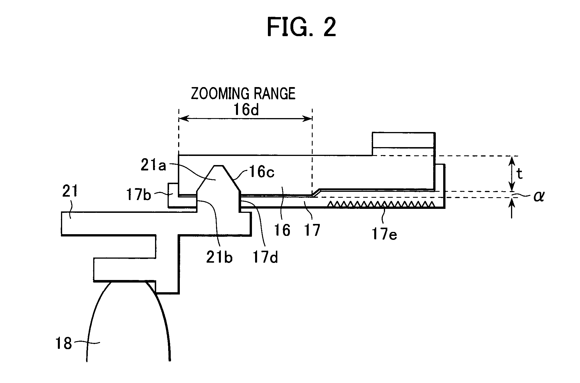
[0039]FIGS. 1 and 2 are schematic diagrams of a lens barrel according to the embodiment of the present invention. In particular, FIG. 1 is a three-dimensional perspective view of the basic structure of the lens barrel, and FIG. 2 is a cross-sectional view of the relevant components of the lens barrel. The basic structure of the lens barrel is similar to that of the conventional one shown in FIGS. 4 to 6 provided with the differential extensible mechanism, and therefore, only the components relevant to the present invention are shown in FIGS. 1 and 2.

[0040]Referring to FIGS. 1 and 2, the lens barrel includes a cam-cylinder 16, a rectilinear cylinder 17, a first-lens-holding cylinder 21, and a first lens 18. These components respectively correspond to the cam-cylinder 116, the rectilinear cylinder 117, the first-lens-holding cylinder 121, and the first lens 118 in FIGS. 4 to 6, and have t...


PUM


Abstract

A lens barrel includes a lens-holding cylinder which supports a lens and is provided with a cam-follower and a rectilinear key; a cam-cylinder having a cam-groove which engages with the cam-follower so as to apply a driving force to the lens-holding cylinder in the optical-axis direction; and a guide cylinder which is enclosed by the cam-cylinder and has a rectilinear guide opening that engages with the rectilinear key so as to guide the lens-holding cylinder in the optical-axis direction. A segment of the cam-cylinder adjacent to an object to be photographed has a greater wall thickness such that the cam-cylinder has a level difference. A portion of the guide cylinder adjacent to an object to be photographed, which corresponds to the level difference of the cam-cylinder, is made thinner by the amount of the level difference.

Description

BACKGROUND OF THE INVENTION[0001]1. Field of the Invention[0002]The present invention relates to extensible lens-barrels used in, for example, cameras.[0003]2. Description of the Related Art[0004]A typical extensible lens-barrel is disclosed in, for example, Japanese Patent Laid-Open No. 2002-277711. This extensible lens-barrel utilizes a differential extensible mechanism in which a differential cylinder and a rectilinear-regulation part rotate relatively with each other such that lens-barrel components disposed adjacent to the corresponding inner and outer peripheries of the differential cylinder and the rectilinear-regulation part are extended or retracted.[0005]FIGS. 4 to 6 illustrate a digital camera which is provided with the lens barrel disclosed in Japanese Patent Laid-Open No. 2002-277711. In detail, FIG. 4 illustrates the operational state of the camera, that is, the state in which the lens barrel is extended. On the other hand, FIG. 6 illustrates the non-operational state ...

Claims


Application Information

Patent Timeline
IPC IPC(8): G02B15/14G02B7/02G02B7/04G02B7/10G03B5/00
CPCG02B7/102G02B7/022
Inventor WADA, HIROYUKI
Owner CANON KK
Features
  • Generate Ideas
  • Intellectual Property
  • Life Sciences
  • Materials
  • Tech Scout
  • Unparalleled Data Quality
  • Higher Quality Content
  • 60% Fewer Hallucinations
Learn More