
Control method and control system for parallel operation between different types of power generator

Active Publication Date: 2015-11-19
KAWASAKI HEAVY IND LTD +1
View PDF1 Cites 6 Cited by
  • Summary
  • Abstract
  • Description
  • Claims
  • Application Information

AI Technical Summary

Benefits of technology

The present invention provides a voltage control method and system for stable and efficient parallel operation between different types of power generators or between a power generator and a system power supply. This allows for stable operation even when generators have different voltage drooping characteristics, and prevents unbalanced load current and stable performance of each power generator. The control method and system can also suppress occurrence of excessive current and step-out in the event of voltage reduction on the system power supply side, thus stably maintaining parallel operation even after voltage of the system power supply is returned. Standards relevant to system interconnection in respective countries require maintaining operation for about 1 to 3 sec even upon occurrence of great voltage reduction.

Problems solved by technology

Therefore, in independent operation, the original performance of the power generators and motors for driving the power generators cannot be exerted, and thus effective operation is hindered.
Regarding an induction power generator, it is not easy for a small-capacity synchronous power generator that is performing independent operation to bear inrush current caused when the induction power generator is applied to parallel operation, and starting current due to the application to parallel operation greatly exceeds a rated current value of the synchronous power generator.
Also in a self-sustaining power conditioner, or a UPS power supply device performing independent operation, it is difficult to perform an operation with induction load, which causes large starting current.

Method used


Image

  • Control method and control system for parallel operation between different types of power generator
  • Control method and control system for parallel operation between different types of power generator
  • Control method and control system for parallel operation between different types of power generator

Examples


Embodiment Construction

[0035]Hereinafter, embodiments of the present invention will be described based on the drawings.

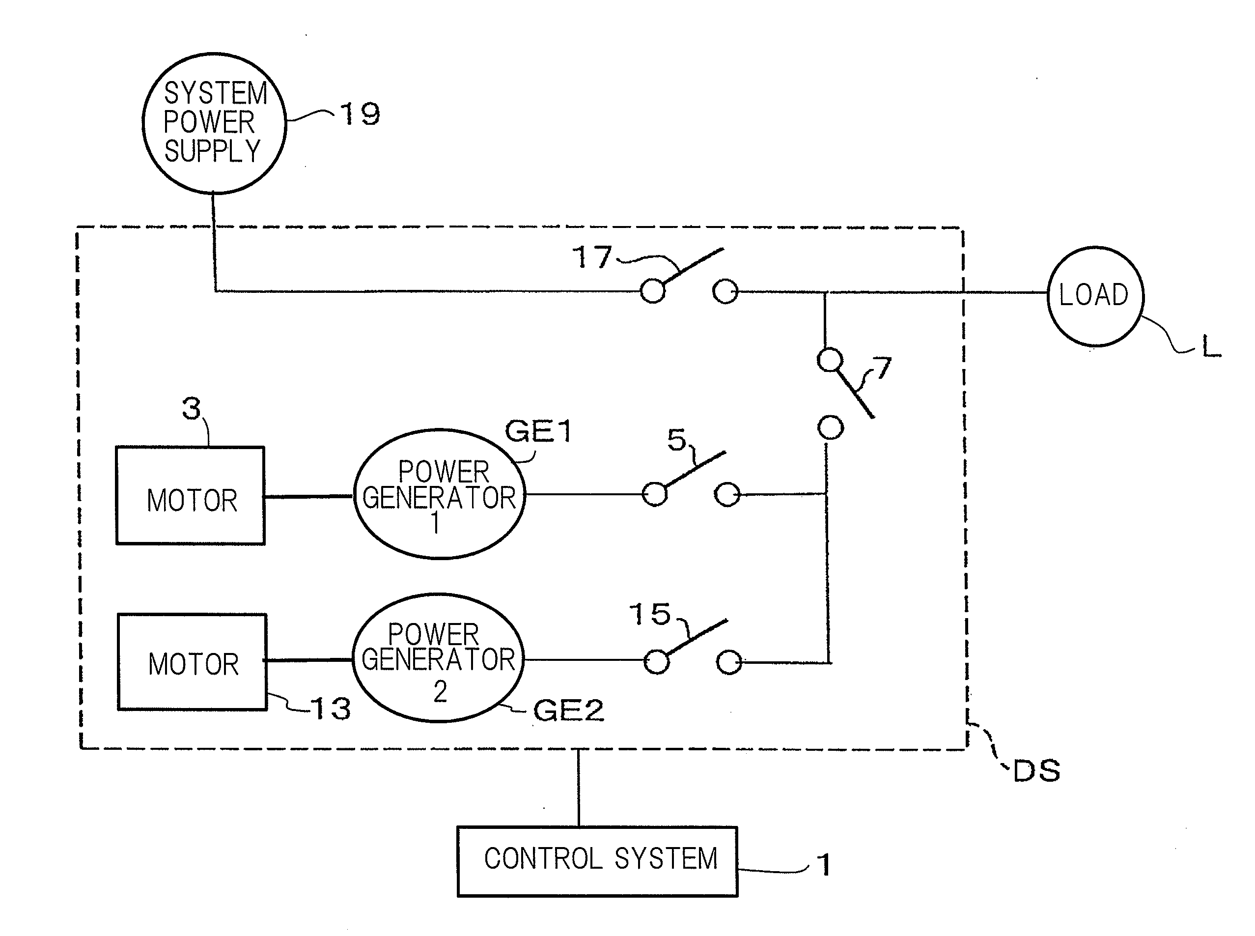
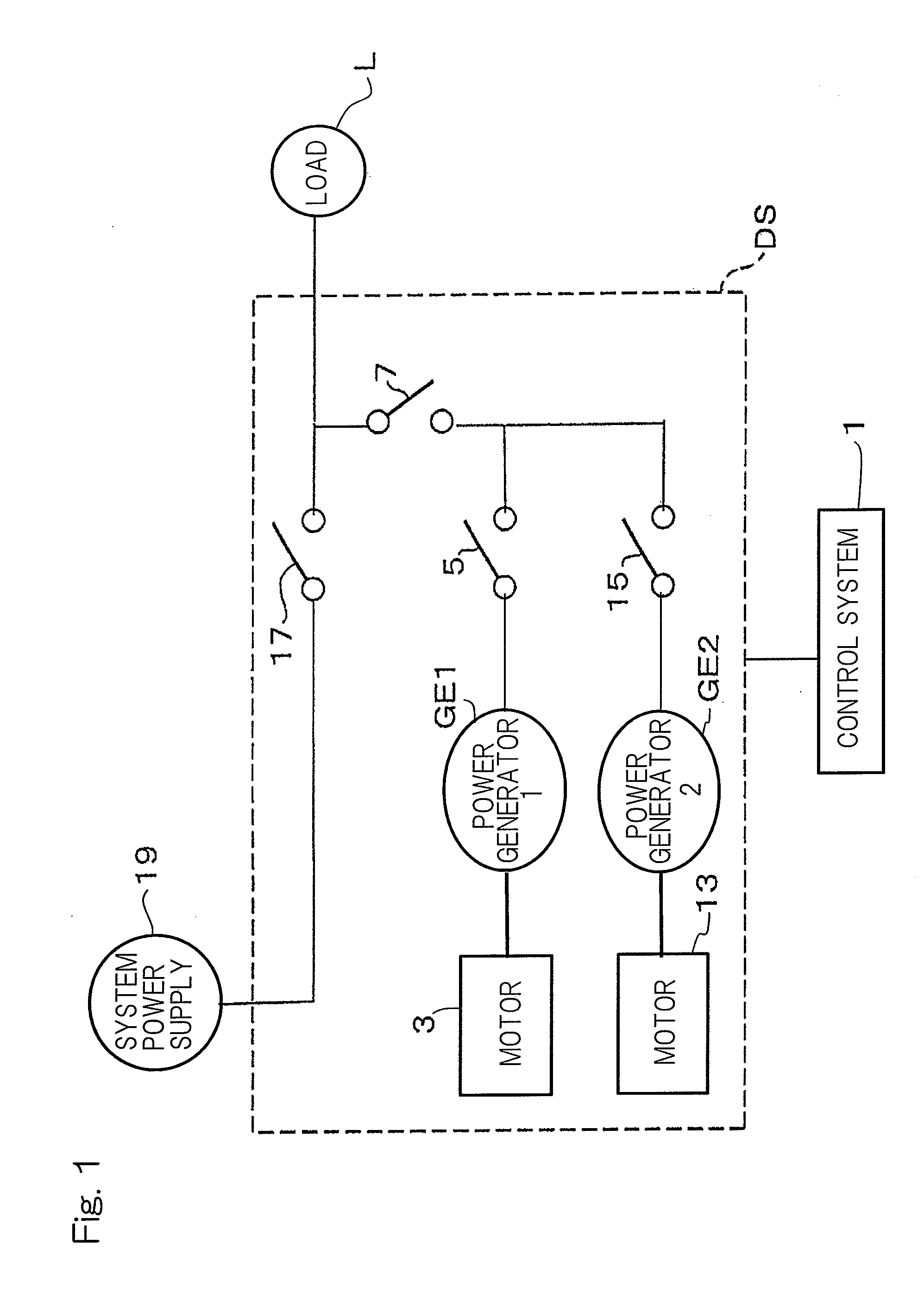
[0036]FIG. 1 shows a schematic configuration of a drive system DS of an apparatus equipped with a control system 1 according to an embodiment of the present invention. The control system 1 is a system for executing a control method according to the embodiment of the present invention. The control method is a control method performed when a plurality of different types of power generators or a power generator and a system power supply having different voltage drooping characteristics, which are characteristics in which output voltage reduces as a load increases, are shifted from respective individual operations thereof to parallel operation for driving the same drive target.

[0037]As used herein, “power generators” to be operated in parallel include, as well as a synchronous power generator of electromagnetic induction type which is driven by a motor having a rotating machine, e.g., a gas t...


PUM


Abstract

In a control method performed in shifting a plurality of different types of power generators to parallel operation, at least one of output voltage and a voltage drooping characteristic of at least one of the plurality of power generators is changed. In the case where the plurality of different types of power generators are a plurality of synchronous power generators having different voltage drooping characteristics, the voltage drooping characteristic of one power generator having a smaller voltage drooping characteristic among the plurality of power generators to be operated in parallel is changed so as to coincide with the voltage drooping characteristic of the other power generator. At the time of changing the voltage drooping characteristic, the other power generator is controlled so that the output voltage thereof is maintained at a value before start of the parallel operation.

Description

CROSS REFERENCE TO THE RELATED APPLICATION[0001]This application is based on and claims Convention priority to Japanese patent application No. 2012-279658, filed Dec. 21, 2012, the entire disclosure of which is herein incorporated by reference as a part of this application.BACKGROUND OF THE INVENTION[0002]1. Field of the Invention[0003]The present invention relates to a control method for stably performing parallel operation between different types of power generators or between a power generator and a system power supply, and to a control system therefor, and particularly relates to a voltage control method performed in shifting to parallel operation and a voltage control system used in shifting to parallel operation.[0004]2. Description of Related Art[0005]Generally, in various power supply facilities, power generators that are normally operated and power generators that are operated in an abnormal case or in an emergency case are separately used according to the types of engines ...

Claims


Application Information

Patent Timeline
IPC IPC(8): H02J3/38
CPCY10T307/505H02J3/381H02J3/46H02P9/02H02P5/00H02J2300/10
Inventor SHIOTA, YUKIHIROCHIDA, MITSURUSATO, KAZUNORITATEISHI, KOUSHICHI
Owner KAWASAKI HEAVY IND LTD
Features
  • Generate Ideas
  • Intellectual Property
  • Life Sciences
  • Materials
  • Tech Scout
  • Unparalleled Data Quality
  • Higher Quality Content
  • 60% Fewer Hallucinations
Learn More