
Disk device having impact absorbing structure for optical pickup unit

Inactive Publication Date: 2005-09-22
ORION ELECTRIC CO LTD
View PDF3 Cites 2 Cited by
  • Summary
  • Abstract
  • Description
  • Claims
  • Application Information

AI Technical Summary

Benefits of technology

[0014] A buffer member integrally formed with the support member may be provided adjacent to the center between the support members for the sub guide rail and upright perpendicularly to the chassis, so that the capability of absorbing impact upon the optical pickup unit is improved.
[0015] Furthermore, one of the buffer member provided at the support member for the main guide rail and the buffer member provided at the support member for the sub guide rail may be shifted from the other in the position so that the timing of the optical pickup unit to strike against the former buffer member is delayed and a larger impact can be smoothly absorbed by this arrangement.
[0017] According to the invention, the buffer members are integrally formed with the support members for the guide rails, and therefore additional time-consuming job is not necessary for producing the buffer members as discrete parts or attaching them. In other words, simply by attaching the main and sub guide rails to the support members having the buffer members integrally, it is possible to protect the optical pickup unit moving beyond the range against impact. In addition, when the buffer members are provided in different positions between the main and sub guide rails, the optical pickup unit strikes against the other buffer member on the main or sub guide rail side after striking against one buffer member on the main or sub guide rail side and greatly deforming the buffer member. Therefore, large impact can be absorbed.

Problems solved by technology

As described above, the optical pickup is the heart of the disk device, and if the pickup is broken, recording / reproducing cannot be carried out correctly.
Consequently, the lens of the optical pickup may be broken or chipped, or errors may be generated in the positioning of the guide rails, and accurate recording / reproducing is no longer possible.
Therefore, the buffer members must be produced as discrete parts and provided in predetermined locations, and additional time-consuming job is necessary for the purpose.
Meanwhile, the attachment may be loosened in the locations and the buffering function may be reduced to a less effective level than intended.

Method used


Image

  • Disk device having impact absorbing structure for optical pickup unit
  • Disk device having impact absorbing structure for optical pickup unit
  • Disk device having impact absorbing structure for optical pickup unit

Examples


Embodiment Construction

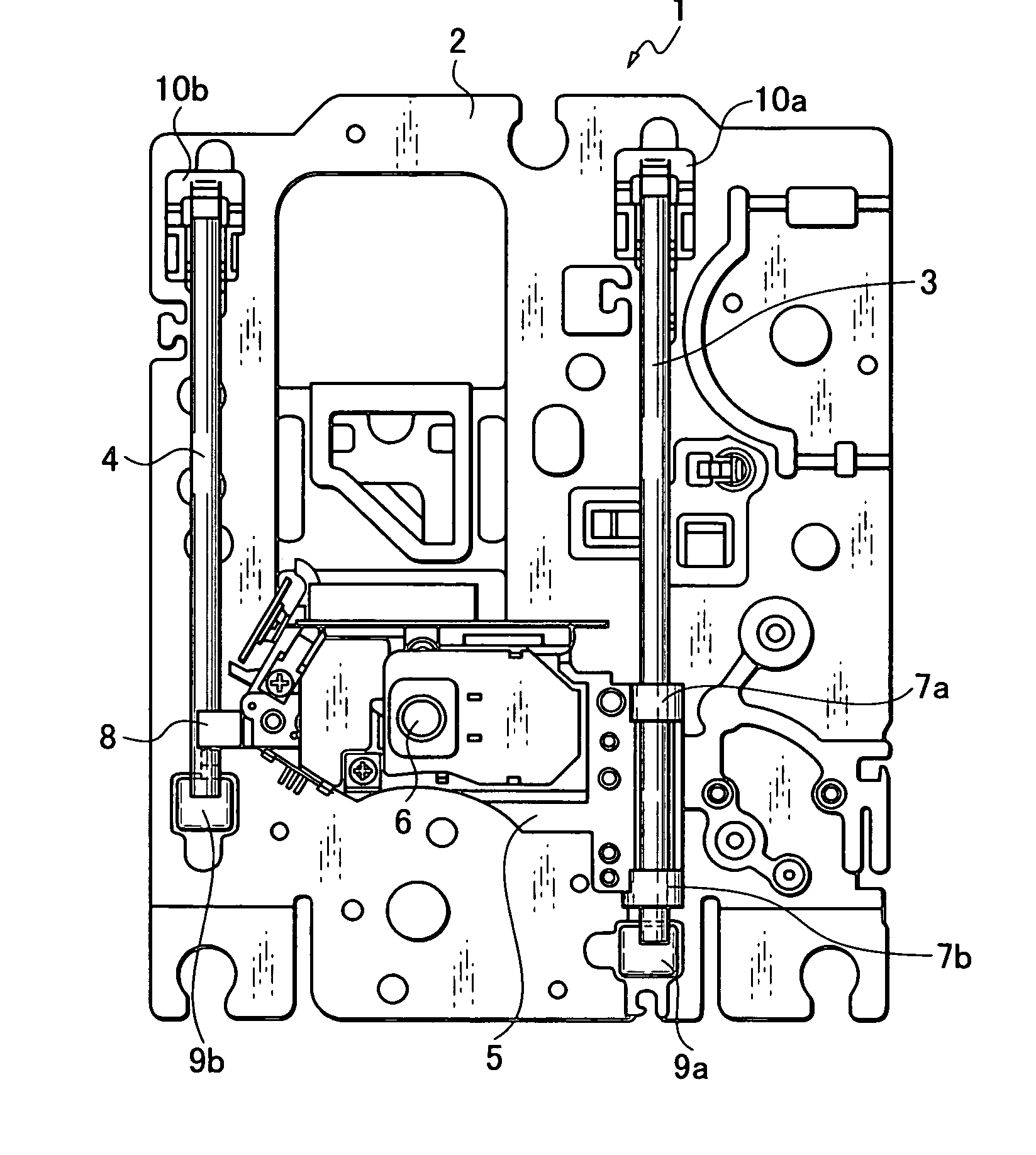
[0024]FIG. 1 shows a traverse unit 1 in a disk device according to an embodiment of the invention. The unit includes a metal chassis 2, a main guide rail 3 and a sub guide rail 4 attached parallel to each other on the chassis 2, and an optical pickup unit 5 including an optical pickup 6. Guide pieces 7a and 7b slidably fitted to the main guide rail 3 are provided on one end side of the optical pickup unit 5, a guide piece 8 that slidably holding the sub guide rail 4 is provided on the other end side. The optical pickup 6 can move along the main guide rail 3 and the sub guide rail 4 as these guide pieces 7a, 7b, and 8 serve as guides.

[0025] The optical pickup unit 5 is provided with a rack engaged with a gear (not shown) and moves as the gear rotates with being driven by a motor. The chassis 2 is provided with a turntable (not shown) to be rotated by a spindle motor, and the optical pickup 6 moves along the main guide rail 3 and the sub guide rail 4 in the radial direction of the di...


PUM


Abstract

To cope with accidental impact inflicted upon an optical pickup unit when the unit moves beyond a prescribed range, resin support members integrally formed with the chassis of a traverse unit and supporting the ends of main and sub guide rails at a prescribed distance are provided on the chassis, so that the impact caused by the collision against the support members for the guide rails is absorbed. Buffer members integrally formed with the support members adjacent to the center and upright perpendicularly to the chassis are provided at least between the support members for the main guide rail, so that the impact upon the optical pickup unit is absorbed.

Description

BACKGROUND OF THE INVENTION [0001] 1. Field of the Invention [0002] The present invention relates to a disk device for such a disk as a mini disk, a magneto-optical disk, or a compact disk, more particularly, to a disk device having an impact absorbing structure for an optical pickup unit mounted at a traverse unit. [0003] 2. Related Art [0004] A traverse unit including a turntable for mounting a disk is provided with an optical pickup. The optical pickup moves along guide rails at a prescribed speed during the rotation of the disk and directs a beam upon the disk to allow recorded information on the disk to be read. The beam from the optical pickup must correctly be directed upon the disk surface in order to read the reflected light accurately. [0005] The disk is mounted on the turntable and rotated at high speed, and the optical pickup moves while tracking control is carried out so that the beam used for reading information follows the information track on the disk, and focus cont...

Claims


Application Information

Patent Timeline
IPC IPC(8): G11B7/08G11B21/02G11B7/085G11B17/00G11B33/08
CPCG11B7/082G11B33/08G11B7/08582
Inventor HARA, HIROTOSHIKOBAYASHI, YUICHI
Owner ORION ELECTRIC CO LTD
Features
  • Generate Ideas
  • Intellectual Property
  • Life Sciences
  • Materials
  • Tech Scout
  • Unparalleled Data Quality
  • Higher Quality Content
  • 60% Fewer Hallucinations
Learn More