Expander locking plier

a technology of locking pliers and pliers, which is applied in the field of locking pliers, can solve the problems of inability to clamp from the outside of the workpiece, and achieve the effect of increasing the torqu

Inactive Publication Date: 2006-02-07
VALTRA
View PDF5 Cites 17 Cited by
  • Summary
  • Abstract
  • Description
  • Claims
  • Application Information

AI Technical Summary

Benefits of technology

[0008]The movable arm is similar in design as a conventional locking plier. At one end the adjustable moving jaw is pivoted and at the other end the elongated release lever is attached. In between but closer to the end with the adjustable moving jaw, a toggle-like member is pivoted. The free end of this toggle-like member is inserted into the inside of the fixed arm and touching the inner end of the rear adjustment screw. The movable arm is connected to the fixed arm through the adjustable moving jaw with pivots and spring. The adjustable moving jaw is fed through the hollow portion in the middle of the J-shape clamping arm. The adjustable moving jaw is equipped with a long screw inserted into a threaded hole so that the length of the protrusion of the screw can be adjusted. Through the rectangular metal block a shorter screw is inserted to form the clamping jaw of the J-shape clamping arm. It is the crossed relationship between the adjustable moving jaw and the J-shape clamping arm that enables the expanding action when the movable arm is pressed against the fixed arm. To adjust for the clamping size and clamping force, the rear adjustment screw is turned clockwise or counterclockwise so that the inner end of the screw will change the position of the toggle-like member and hence the angular position of the adjustable moving jaw. If stronger clamping force is needed, a metal rod, a screw driver or any tool with a rod of the right size can be inserted into the cylindrical hole on the rear adjustment screw to turn it with the larger torque required.
[0009]The expanding action of the present invention makes internal clamping possible. Workpieces can be clamped between two opposite surfaces of a fixture or another workpiece, or clamped inside a tube. Another useful application of the present invention is to expand two workpieces or two portions of a workpiece apart with desired amount of force. The effective clamping size of the invention is adjustable by the screw and thread design of the adjustable moving jaw and the jaw attached to the J-shape clamping arm.

Problems solved by technology

Although not so common in the field, there are situations where clamping from the outside of a workpiece is not possible.

Method used


Image

  • Expander locking plier
  • Expander locking plier
  • Expander locking plier

Examples


Embodiment Construction

[0013]With the help of the drawings and the detail description below, the features of the present invention will be apparent and fully understandable.

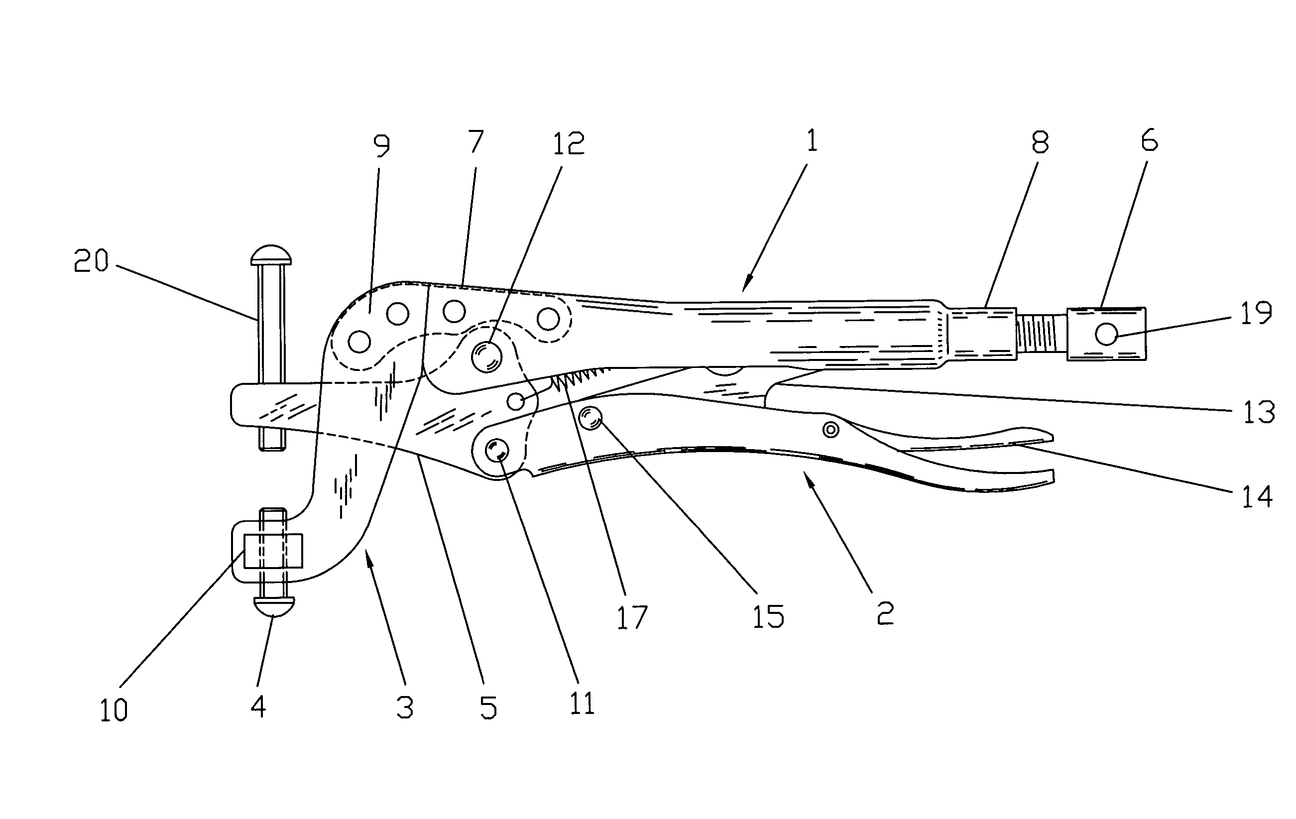
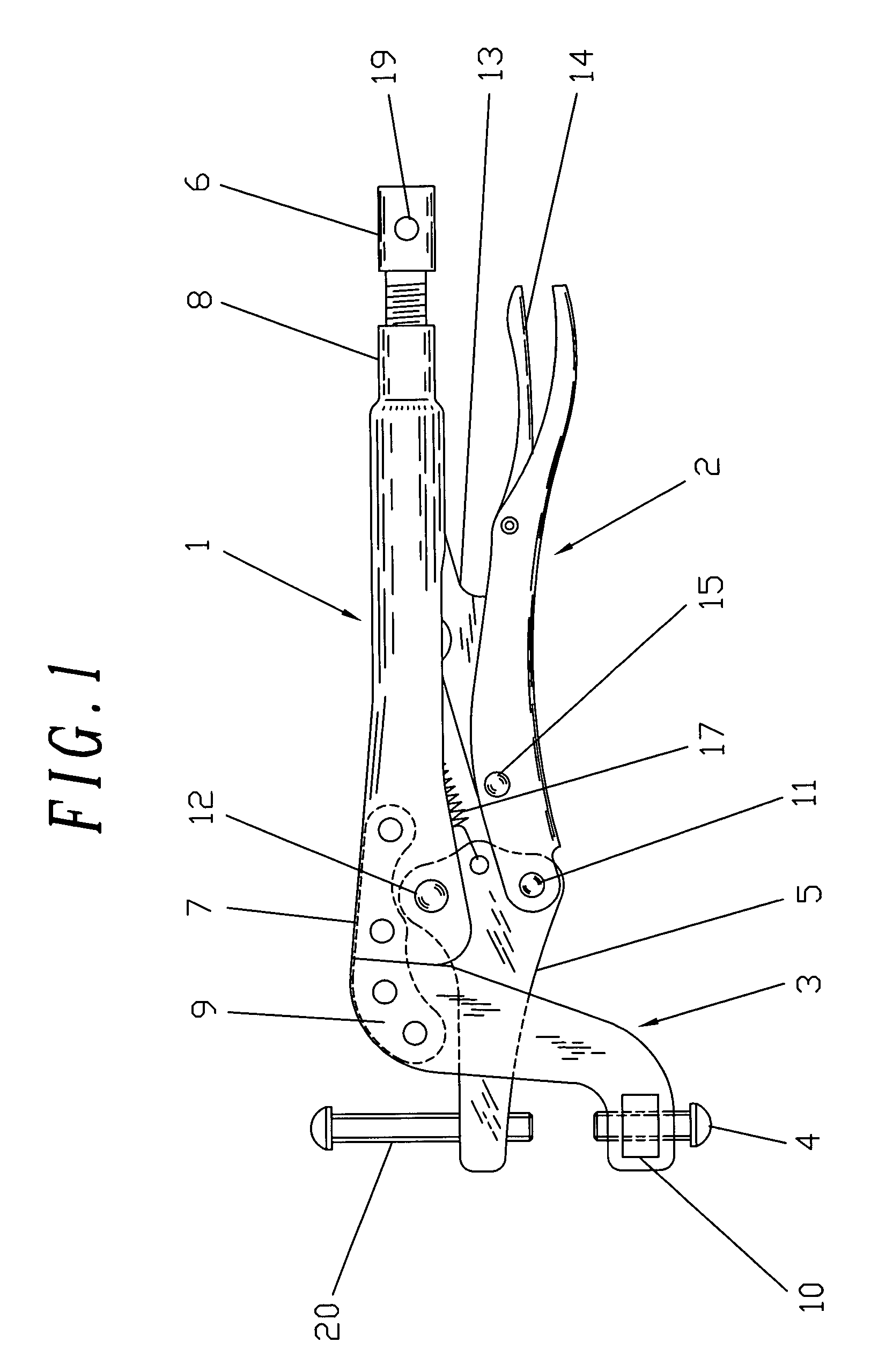
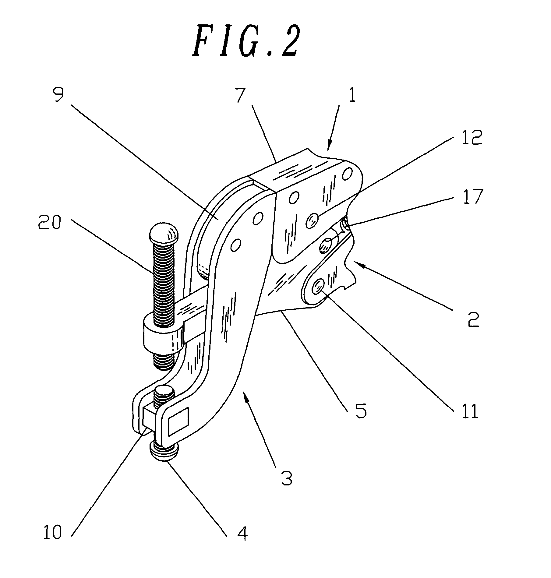
[0014]Referring to FIG. 1, the expander locking plier comprises a fixed arm 1, a movable arm 2 with self-locking and quick release mechanism, a J-shape clamping arm 3 with adjustable jaw 4, an adjustable moving jaw 5 and a rear adjustment screw 6. Resembling the fixed handle of a conventional locking plier without the clamping jaw, the crossed section of fixed arm 1 is U-shape at one end 7 and cylindrical shape at the other end 8 which is threaded inside. The straight portion of a L-shape metal plate 9 is fixed to end 7 with two rivets. The J-shape clamping arm 3 is made of two J-shape metal plates welded together with a rectangular metal block 10 at the smaller ends. The bigger end of the J-shape clamping arm 3 is riveted to the curved end of the L-shape metal plate 9. Hence the J-shape clamping arm 3 is hollow in the middle part so t...


PUM


Abstract

A clamping device utilizes the mechanism of conventional vise-grip locking pliers to clamp internally or to expand workpieces with adjustable force. The invention comprises a fixed arm, a movable arm with quick release mechanism, a pair of special design, crossed clamping arms with jaws. Also included with the invention is the rear adjustment screw attached to one end of the fixed arm for setting the clamping gap and the clamping force.

Description

[0001]Note: This application is based on my provisional patent application filed on Sep. 16, 2002 with application No. 60 / 410,440.REFERENCE CITED U.S. PATENT DOCUMENTS[0002]2,590,031March 1952Christian Petersen2,641,149June 1953Christian Petersen3,585,704June 1971J. A. Schroeder4,305,575December 1981Dale L. Bardes4,386,542June 1983Louis R. Verna4,477,937October 1984James Costello4,730,524March 1988Christian Petersen5,022,290June 1991Thomas F. Duffy5,305,669April 1994Gary A. KimbroBACKGROUND OF THE INVENTION[0003]1. Field of the Invention[0004]The present invention relates to a class of locking pliers, or vise-grips in general, and more particularly to expander locking plier with easily adjustable clamping force. The invention is capable of clamping one or two workpieces against the internal surfaces of a tube, a fixture or another workpiece with adjustable clamping force. It is also capable to expand two portions of a workpiece or two workpieces apart by turning the rear adjustment ...

Claims


Application Information

Patent Timeline
Patent Type & Authority Patents(United States)
IPC IPC(8): B25B7/12B25B7/02B25B7/04
CPCB25B7/02B25B7/123B25B7/04
Inventor WONG, HARRY
Owner VALTRA
Why Eureka
Try Eureka