Assembling structure of indicating needle for instrument and assembling method

a technology of assembling structure and indicating needle, which is applied in the directions of identification means, instruments, transportation and packaging, etc., can solve the problems of gear deformation, insufficient protection of lower case b>2/b> from deformation, and difficulty in assembling the structur

Active Publication Date: 2006-02-07
CALSONIC KANSEI CORP
View PDF6 Cites 13 Cited by
  • Summary
  • Abstract
  • Description
  • Claims
  • Application Information

AI Technical Summary

Benefits of technology

[0011]It is, therefore, an object of the present invention to provide an assembling structure of an indicating needle for an instrument and an assembling method which can assemble an indicating needle without deforming a lower case while protecting a projection of a leading end of lower end portion of an indicating needle shaft from the bottom surface of the lower case.
[0013]According to the above described structure, the leading end of the lower end portion of the indicating needle shaft is settled into the concave portion, and is not projected from the bottom surface of the lower case, so that packaging becomes easy. Moreover, a rim of a through-hole is hardly hit by another component, enabling the protection of the flash generated on the rim of the through-hole to be entered into the through-hole, so that the stabilized rotation of the indicating needle shaft is ensured.

Problems solved by technology

The case body including the lower case 2 is made of synthetic resin, and if the case body 3 locally receives considerable strength, it is deformed and causes problems for the strength.
However, the method is not enough for protecting the lower case 2 from the deformation, and also the gear may be deformed.
Therefore, there is a problem if the lower end portion of the indicating needle is inserted into the through-hole, the leading edge of the lower end portion of the indicating needle shaft is projected from the bottom surface of the lower case.
Moreover, there may be a case that the indicating needle may be deformed by shock from the outside.
Moreover, for the prior art, the opening edge portion of the through-hole and the bottom surface of the lower case have the same height, so that the rim of the through-hole is easy to be hit by another component, and if the rim of the through-hole is hit by another component, flushes are entered inside the through-hole, and it becomes a problem for stabilizing the rotation of the indicating needle shaft.

Method used


Image

  • Assembling structure of indicating needle for instrument and assembling method
  • Assembling structure of indicating needle for instrument and assembling method
  • Assembling structure of indicating needle for instrument and assembling method

Examples


Embodiment Construction

[0024]Hereinafter, an embodiment of the present invention will be described with accompanying views.

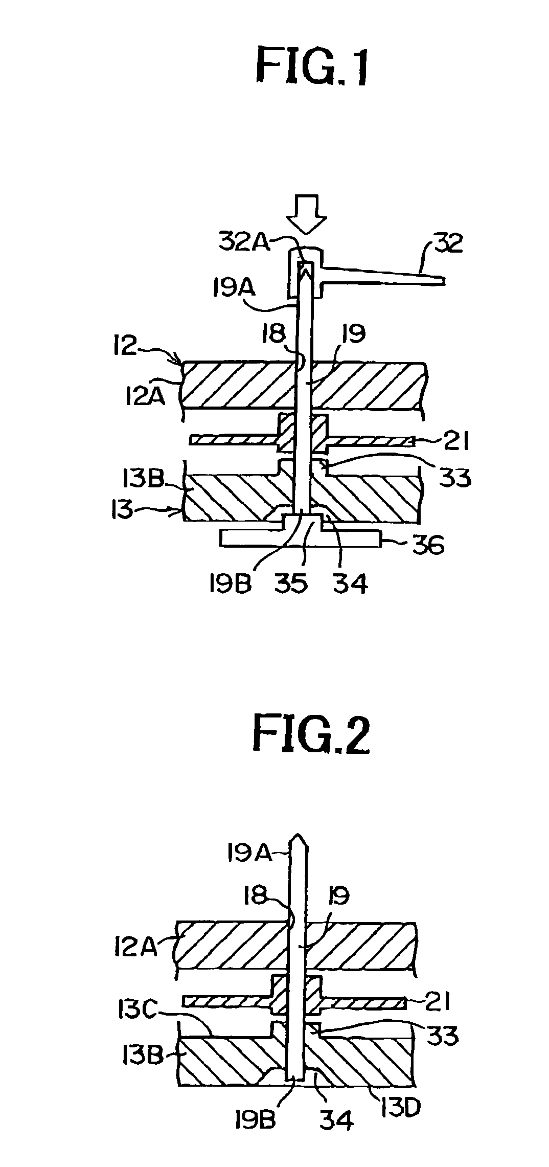
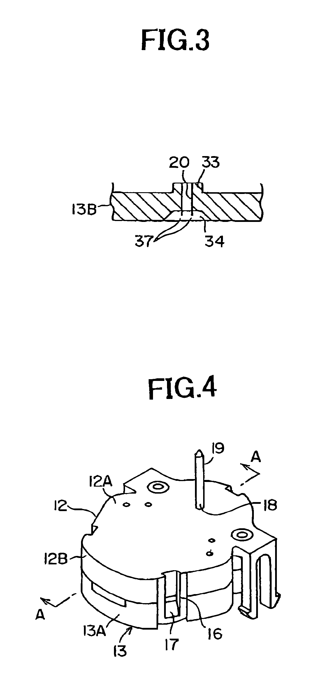
[0025]FIGS. 4 to 6 illustrate stepping motor incorporated instruments according to the present embodiment, and FIG. 4 is a perspective view of the external appearance, FIG. 5 is the disassembled perspective view, and FIG. 6 is the cross sectional view along the line A—A in FIG. 4.

[0026]As illustrated in FIGS. 4 to 6, a stepping motor incorporated instrument 10 comprises a case body 11 made of synthetic resin, and the case body 11 includes an upper case 12 and a lower case 13. A pair of holes 14 is provided on an upper wall 12A of the upper case 12, and a pair of projections 15 corresponding to the holes 14 is provided on a side wall 13A of the lower case 13. The upper case 12 is aligned with the lower case 13 by fitting the projections 15 into the holes 14. A piece 16 is disposed on a side wall 12B of the upper case 12, and a projection 17 is disposed on the side wall 13A of the lower...


PUM


Abstract

A assembling structure of an indicating needle for an instrument includes a case body having an upper case and a lower case (13), an indicating needle shaft (19) rotatably pivoted by the upper case and the lower case, and a top portion (19A) of the indicating needle shaft is projected to outside from the upper caser (13), and an indicating needle (32) provided on the projection. A concave portion (34) is provided on a shift supporting portion of the indicating needle shaft (19) in a bottom surface of the lower case, a lower end portion (19B) of the indicating needle shaft (19) is projected into the concave portion (34), and the projection amount is smaller than the depth of the concave portion (34).

Description

BACKGROUND OF THE INVENTION[0001]1. Field of the Invention[0002]The present invention relates to an assembling structure and an assembling method of an indicating needle to an indicating needle shaft in a stepping motor incorporated instrument.[0003]2. Description of Prior Art[0004]Generally, an instrument such as a speed meter for a vehicle, and the like is provided with a case body 3 comprising an upper case 1 and a lower case 2, and an indicating needle 5 is rotatably pivoted at an upper portion to the upper case 1, and at a lower portion to the lower case 2, respectively, and also has a gear 4 at an intermediate portion. A top portion 5A of the indicating needle shaft 5 is projected outside from the upper case 1, and is provided with an indicating needle 6.[0005]A press fit method is generally used for assembling the indicating needle 6 to the top portion 5A of the indicating needle shaft 5. That is, generally, the case body 3 is flatly placed on a base (not shown), directing th...

Claims


Application Information

Patent Timeline
Patent Type & Authority Patents(United States)
IPC IPC(8): G01D13/00G01D13/22B60K35/00G01D11/24H02K37/16
CPCG01D11/24Y10S116/06G01D2213/10
Inventor ABE, SHOTAROTAKAHASHI, HIDEYUKI
Owner CALSONIC KANSEI CORP
Why Eureka
Try Eureka