Seat backrest cover module

a backrest cover and module technology, applied in the field of vehicle seats, can solve the problems of relative cost and heavyness of the back frame, and achieve the effect of reducing the cost of backrest cover

Inactive Publication Date: 2006-02-07
LEAR CORP
View PDF56 Cites 49 Cited by
  • Summary
  • Abstract
  • Description
  • Claims
  • Application Information

AI Technical Summary

Benefits of technology

[0005]This invention relates to a vehicle seat assembly including a frame formed of at least two components made of different materials to provide a relatively strong yet lightweight frame. The seat assembly includes a seat back frame having a pair of spaced apart sid

Problems solved by technology

These back frames are generally made of m

Method used


Image

  • Seat backrest cover module
  • Seat backrest cover module
  • Seat backrest cover module

Examples


Embodiment Construction

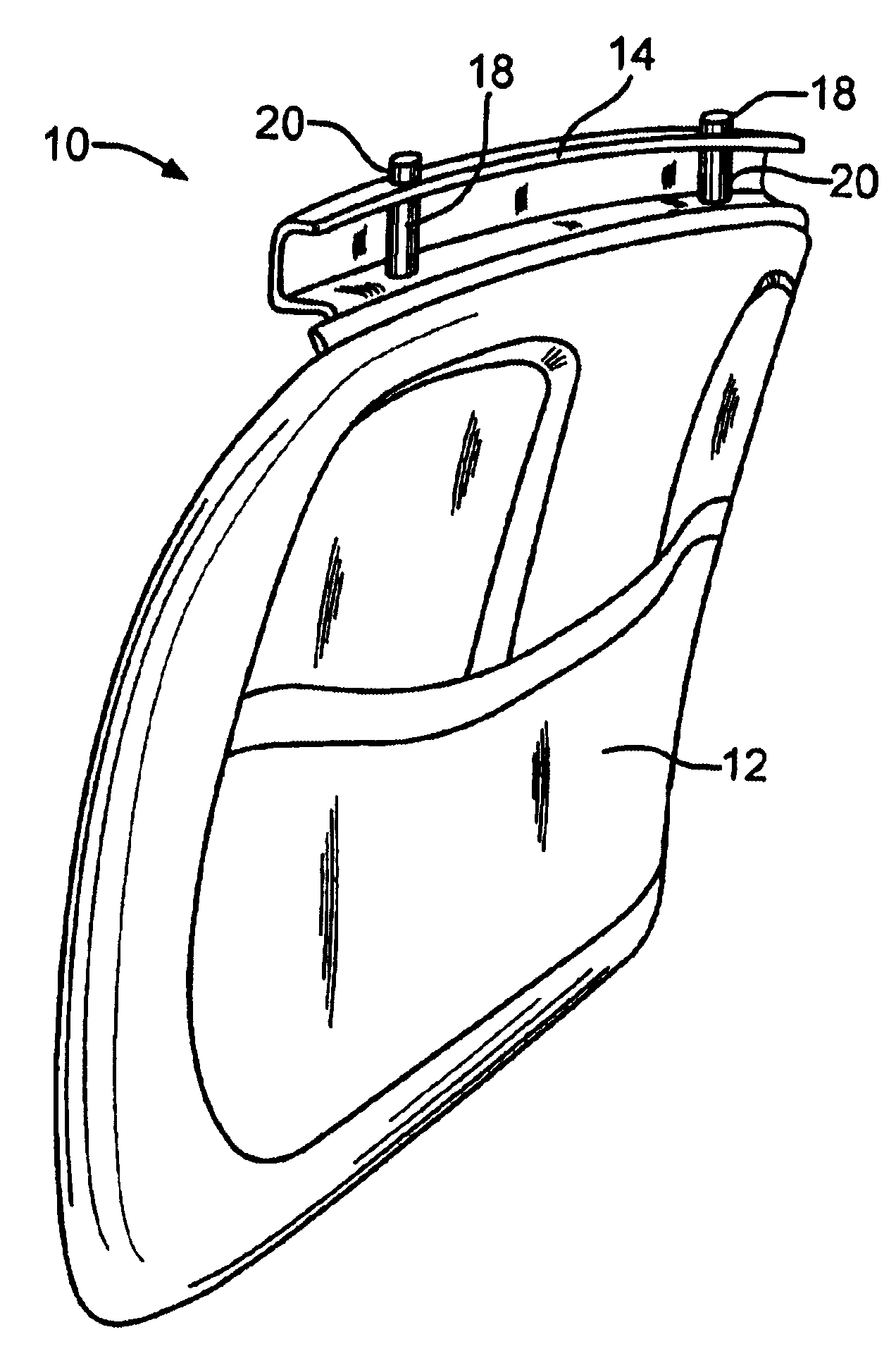
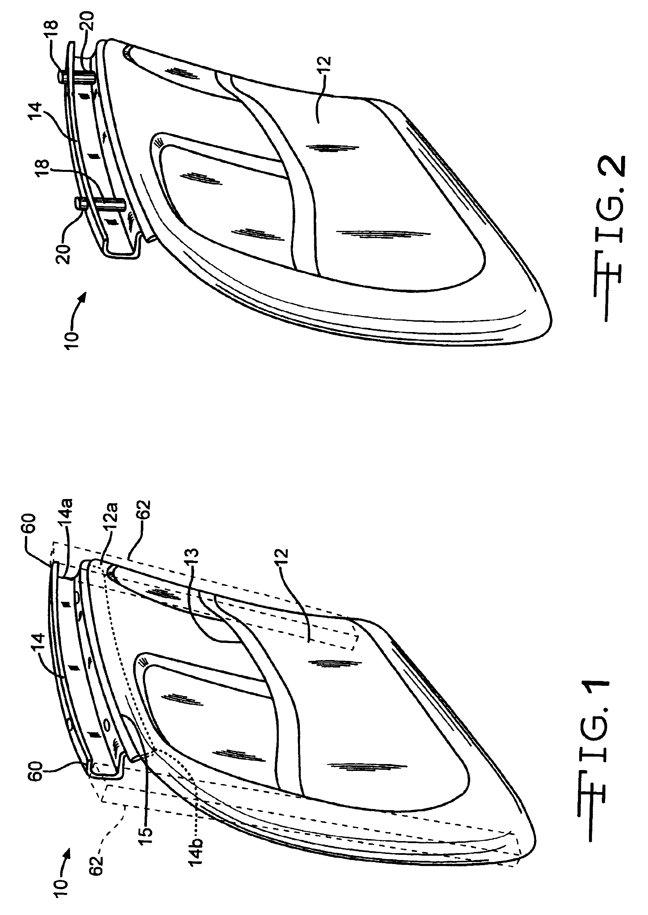
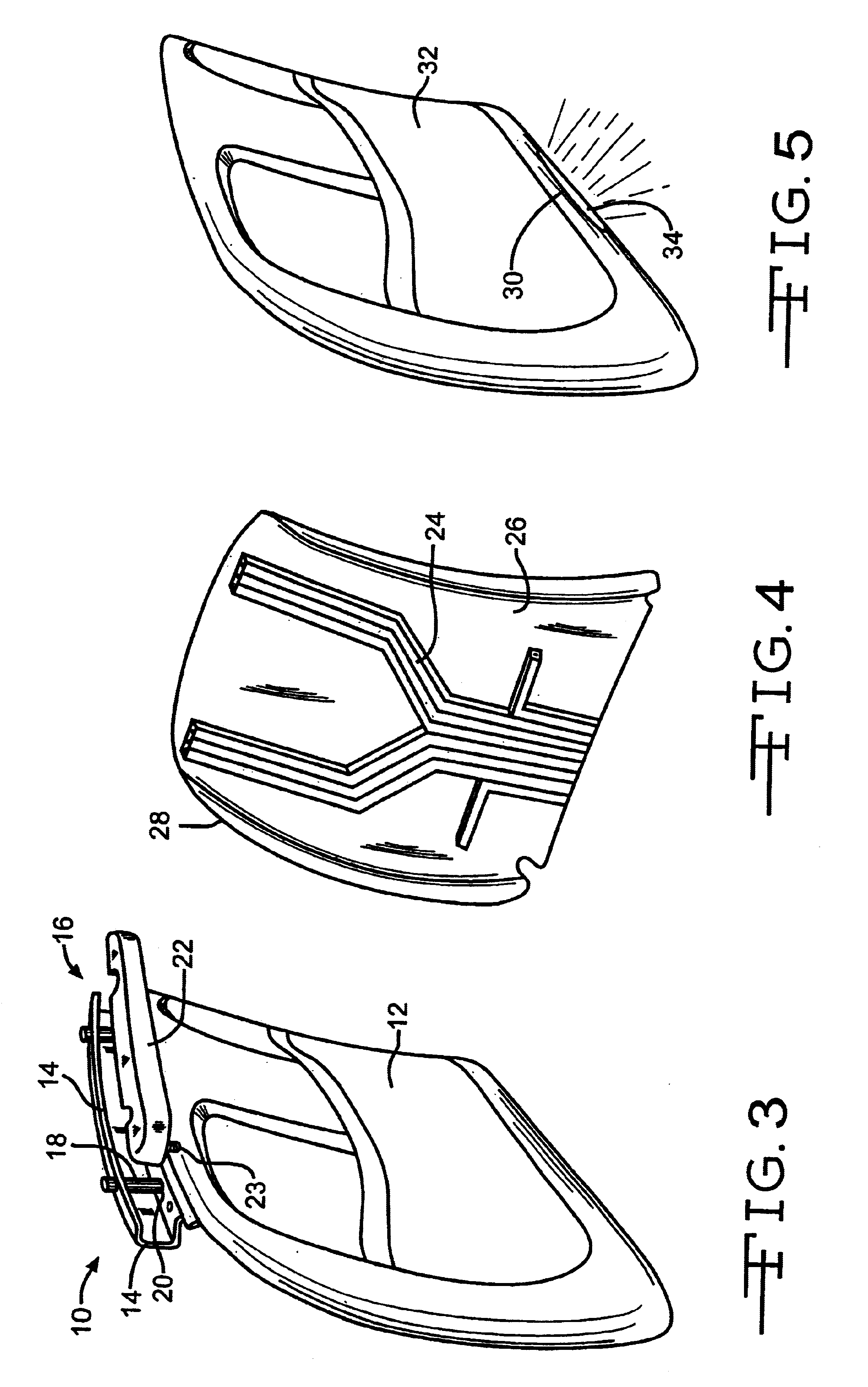
[0016]The present invention relates to a backrest cover module which improves the structural integrity of the seat back and reduces the cost of assembling the vehicle seat by providing the backrest cover module with various vehicle components which are pre-assembled on the cover. For example, multiple housings for the plurality of components may be eliminated. The term “pre-assembled” generally means that the components are attached or formed integrally with the backrest cover prior to installation of the cover to the seat frame. The cover can also include an integral structural cross member to provide stiffness for the vehicle seat. Different embodiments of the invention are illustrated in the accompanying drawings.

[0017]There is illustrated in FIG. 1 an embodiment of a backrest cover module, indicated generally at 10, for use in covering a rear portion of a vehicle seat. The module 10 generally includes a backrest cover 12 and cross member 14. The cover 12 can be made of any suita...


PUM


Abstract

A seat assembly includes a seat back frame having a pair of spaced apart side rails. A cover is fastened to the frame and extends between the pair of side rails. A rigid cross member is preferably integrally molded in an upper portion of the cover. The cover and the cross member cooperate to provide structural rigidity to the seat back frame.

Description

CROSS REFERENCE TO RELATED APPLICATIONS[0001]This application claims the benefit of U.S. Provisional Application No. 60 / 232,525 filed Sep. 14, 2000.BACKGROUND OF THE INVENTION[0002]This invention relates in general to vehicle seats, and in particular to a backrest cover module for a vehicle seat including various vehicle components preassembled on the backrest cover.[0003]Seats for passenger vehicles commonly have a U-shaped structural back frame having a pair of vertical side members joined together by a horizontally extending cross member positioned near the upper portion of the seat back. Often, these back frames are formed from tubular stock material which is bent to form the upper corners of the seat back. These back frames are generally made of metal and are relative expensive and heavy. A lightweight relatively flimsy plastic back cover is commonly used to cover the rear portion of the seat back. These conventional plastic covers are aesthetic in purpose and are fastened to t...

Claims


Application Information

Patent Timeline
IPC IPC(8): A47C7/02
CPCA47C7/725B60N2/58B60N2002/0264B60N2/0264
Inventor FISCHER, HARALDWALK, HANS JORGSCHUMM, VOLKERRAGER, BERND
Owner LEAR CORP
Why Eureka
Try Eureka