
Roll-forming machine for gutter cap and method for making same

a technology of gutter cap and rolling machine, which is applied in the direction of roof covering, roof construction, roofs, etc., can solve the problems of affecting the efficiency of rain gutters, affecting the flow of water, and accumulating along the wire mesh would then present an emergent obstacle, so as to increase the flow of water.

Inactive Publication Date: 2006-01-05
WIRBEL LOUIS
View PDF4 Cites 6 Cited by
  • Summary
  • Abstract
  • Description
  • Claims
  • Application Information

AI Technical Summary

Benefits of technology

[0009] It is an object of the instant invention to substantially increase the flow of water from a gutter cap into an underlying gutter trough.
[0010] It is another object of the instant invention to produce a gutter cap that can be formed from a continuous length of metal without the need for creating spices, butt-joints or overlapping joints.
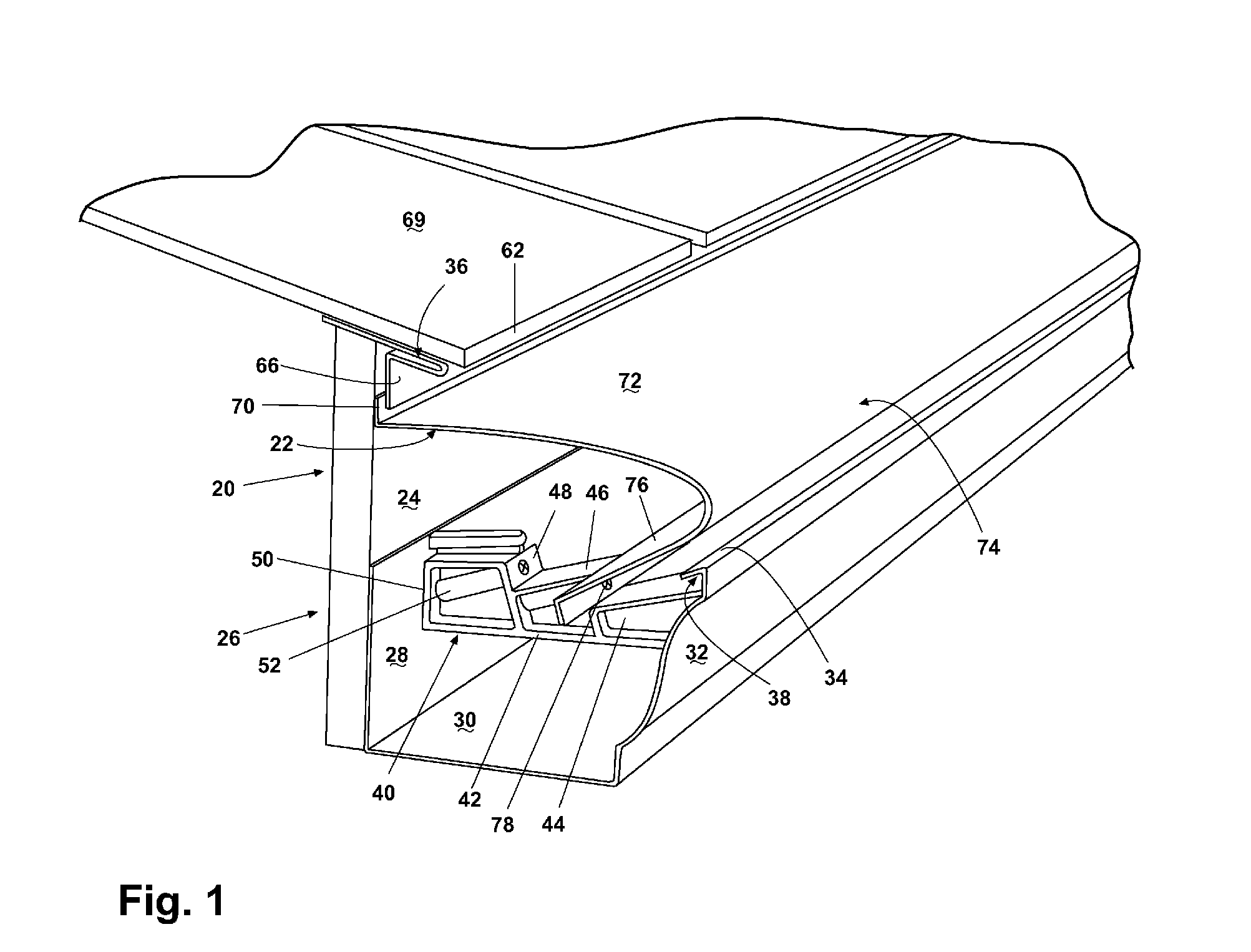
[0013] According to another form of the invention, a gutter trough is attached to the fascia board of a building a predetermined distance below the drip edge of the roof. A mounting bracket having a number of stepped segments engages the outer most edge of the gutter to provide structural rigidity for the trough. The opposite end of the mounting bracket engages the opposite surface of the gutter trough. At least one fastener is passed through the mounting bracket and into the underlying fascia board to hold the gutter trough in position.
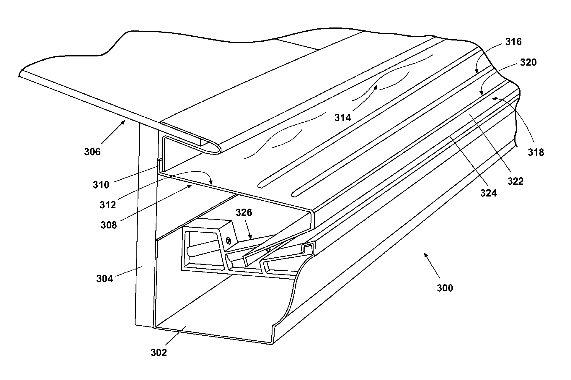
[0016] In each of the embodiments described above, the flow of the water down the upper surface of the gutter cap is dispersed to generally form a sheet. Because of surface tension (molecular attraction) between the substrate and the water, the water flows substantially evenly over the cap surface. As the water approaches the nose, the adhesion property directs the water around the nose and into the gutter trough. In the embodiments where a water break or flange is provided above the trough, the water impacting the flange is redirected in a spray-like fashion into the trough. This intentional agitation of the runoff water helps keep small particles of detritus in suspension to flow down gradient. Larger debris entrained in the water runoff over the gutter cap is unable to remain in suspension and is forced over the nose and away from the gutter trough, leaving the gutter free of clogging debris.
[0017] The advantages of the instant invention include the dispersal effect of the water on the cap surface, increasing the adhesion property of the water to the surface and increasing the amount of water deposited within the trough. Another advantage of the instant invention is the capture of a substantial portion of the water runoff as a result of the water passing into the perforated opening up slope surface of the cascading ridges or ripples. Another advantage of the instant invention is the unique mounting bracket used to mount the gutter trough to the fascia board and its function of anchoring the lower edge of the cap within the trough. The mounting bracket, in combination with the downwardly depending flange of the cap continuously agitates the water, keeping small sediment in suspension as it moves along the trough and down the downspouts. This results in a cleaner trough and improved water flow.

Problems solved by technology

The efficiency of rain gutters is substantially hampered by the amount of debris and detritus within the troughs.
The debris accumulating along the wire mesh would then present an emergent obstacle that would divert water runoff at angles that often overshot the trough.
Over time, the debris field on top of the wire mesh often caused a collapse of the mesh such that the debris ultimately dammed the water flow to the drain pipe.
The adhesion coefficient for debris was much lower resulting in the debris being swept off the end and onto the ground below.
However, depending upon the amount of rainfall, the radius of curvature was too great, resulting in water cascading off of the radius curve and falling onto the ground, essentially defeating the purpose of the gutter guard in the first place.
Another disadvantage with gutter cap systems is that they are precut into fixed lengths.
At times, these precut lengths are insufficient to span the entire distance of a single run, resulting in the need to splice and overlap joints.
Coefficients of expansion and contraction also influenced these caps, causing the caps to become dislodged and unsightly.

Method used


Image

  • Roll-forming machine for gutter cap and method for making same
  • Roll-forming machine for gutter cap and method for making same
  • Roll-forming machine for gutter cap and method for making same

Examples


Embodiment Construction

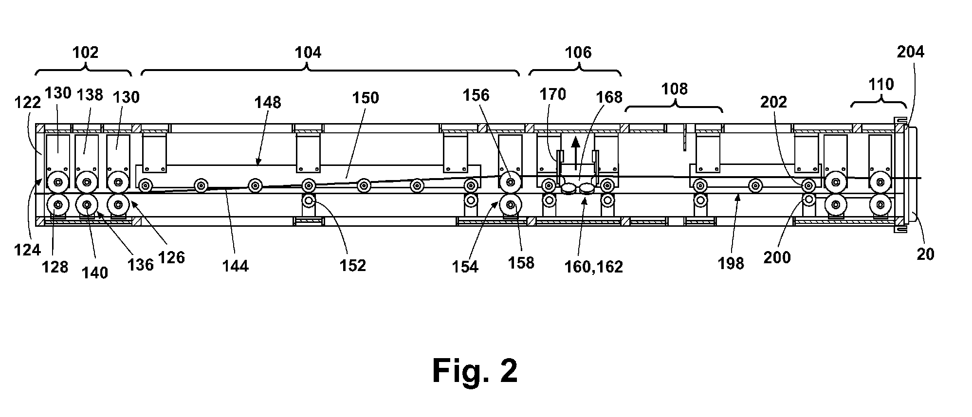
[0036] The instant invention include a novel cap for a rain gutter intended to exclude debris, yet capture water runoff from the roof structures of buildings and the like. In combination with the novel gutter cap is a novel and unique bracket used to mount a rain gutter to a fascia board of the structure. In addition, a unique method and machine are disclosed for making this inventive gutter cap.

[0037]FIG. 1 generally illustrates an embodiment of a rain gutter assembly 20 including a rain gutter 22 having a predetermined profile and mounted to a fascia board 24 of a structure or building 26. In this particular case, the rain gutter 22 includes an inside vertical flange 28 integral with a bottom flange 30 extending generally perpendicular there from. Extending upward from the distal edge of the flange 30 is an outer flange 32 often shaped into a decorative profile. In the rain gutter 22 shown, the outer flange 32 terminates with a capture surface 34 inclined in towards the interior ...


PUM

PropertyMeasurementUnit
radiusaaaaaaaaaa
widthaaaaaaaaaa
widthaaaaaaaaaa

Abstract

A novel roll-forming machine is disclosed for making caps to cover rain gutters and prevent the entry of debris into the rain gutters that cause damming and overflow. The roll-forming machine may be used in a predetermined manner to manufacture caps of different profiles in substantially any desired length, thus substantially reducing the number of joints between adjacent sections and increasing the amount of water run-off captured within the rain gutters. Also disclosed is a unique rain gutter cap profile substantially complementing the generally angular design of standard rain gutters while still maximizing the redirection of water into the underlying rain gutter while keeping potentially clogging debris from entering the rain gutter.

Description

CROSS-REFERENCE TO RELATED APPLICATION [0001] This application claims priority from U.S. Provisional Patent Application filed Jul. 1, 2004 and assigned application Ser. No. 60 / 584,932, the contents of which are incorporated herein by reference.BACKGROUND OF THE INVENTION [0002] 1. Field of the Invention [0003] This invention relates to devices for diverting water from a surface and particularly to a unique device for reducing the amount of detritus allowed to fill a rain gutter while maximizing the diversion of water into the gutter. This invention also relates to a method and apparatus for manufacturing such a device as well as a unique gutter cap configuration. [0004] 2. Discussion of the Related Art [0005] Gutters are mounted to the drip edges of houses and other structures to capture water runoff from the roof structures and divert the water to predetermined locations. These traditional structures consist of a trough attached to the fascia board or similar structure adjacent the...

Claims


Application Information

Patent Timeline
Patent Type & Authority Applications(United States)
IPC IPC(8): E04D13/00
CPCE04D13/076B21D5/08
Inventor WIRBEL, LOUIS
Owner WIRBEL LOUIS
Learn More