

Apparatus and system for clearing a roadway surface
- Summary
- Abstract
- Description
- Claims
- Application Information
AI Technical Summary
Benefits of technology
Problems solved by technology
Method used
Image

Examples
Embodiment Construction
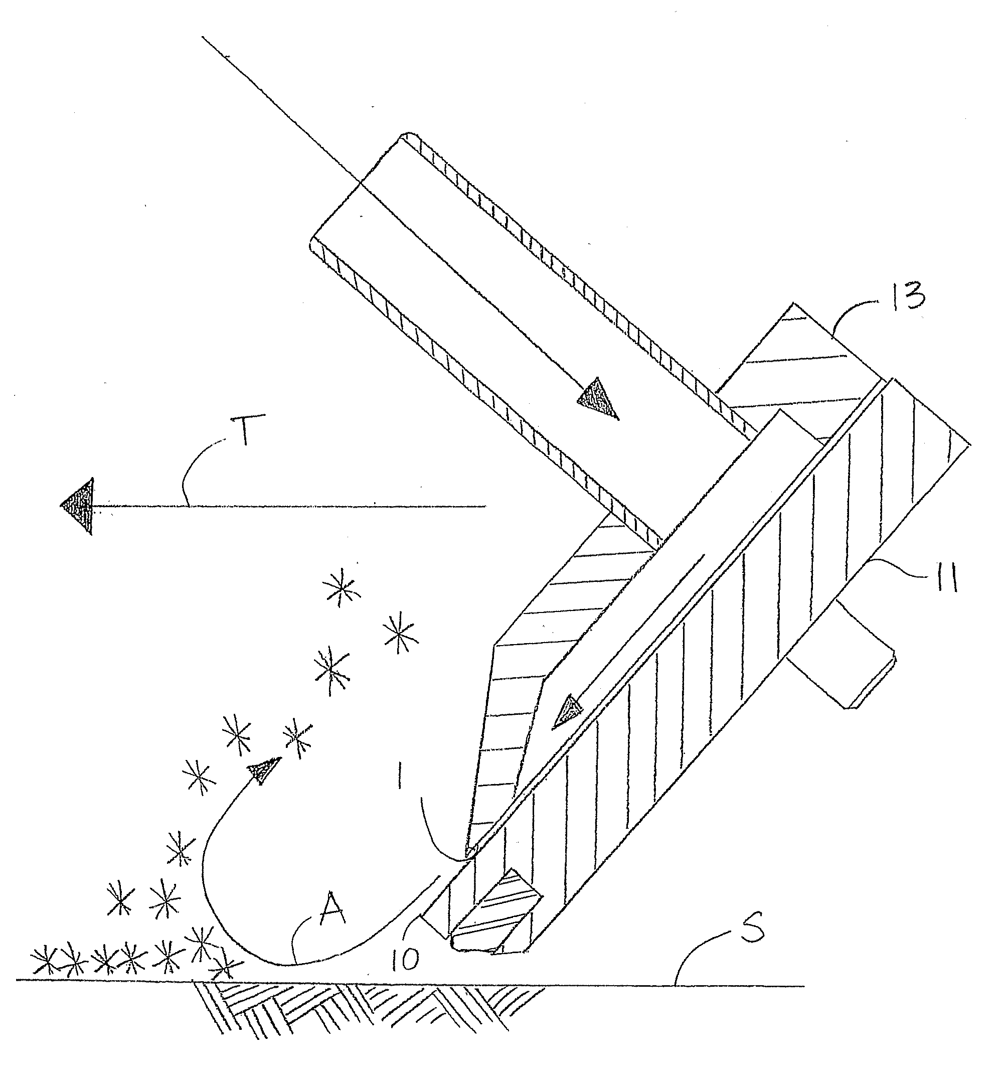
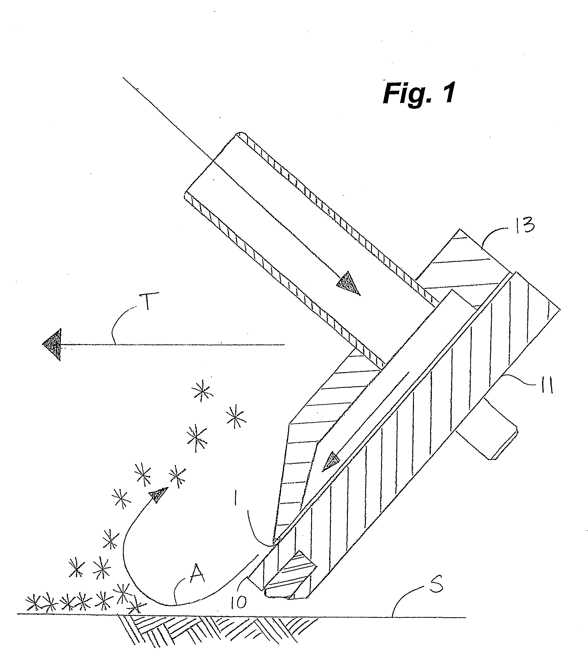
[0049] Embodiments of the invention disclosed herein are described in the context of apparatus for attachment to a conventional scraper blade, such as used on a snow plow. One of skill in the art would appreciate however that embodiments of the invention can be attached to any equipment which can be passed over a surface to be cleared of snow, ice, water, debris and the like.
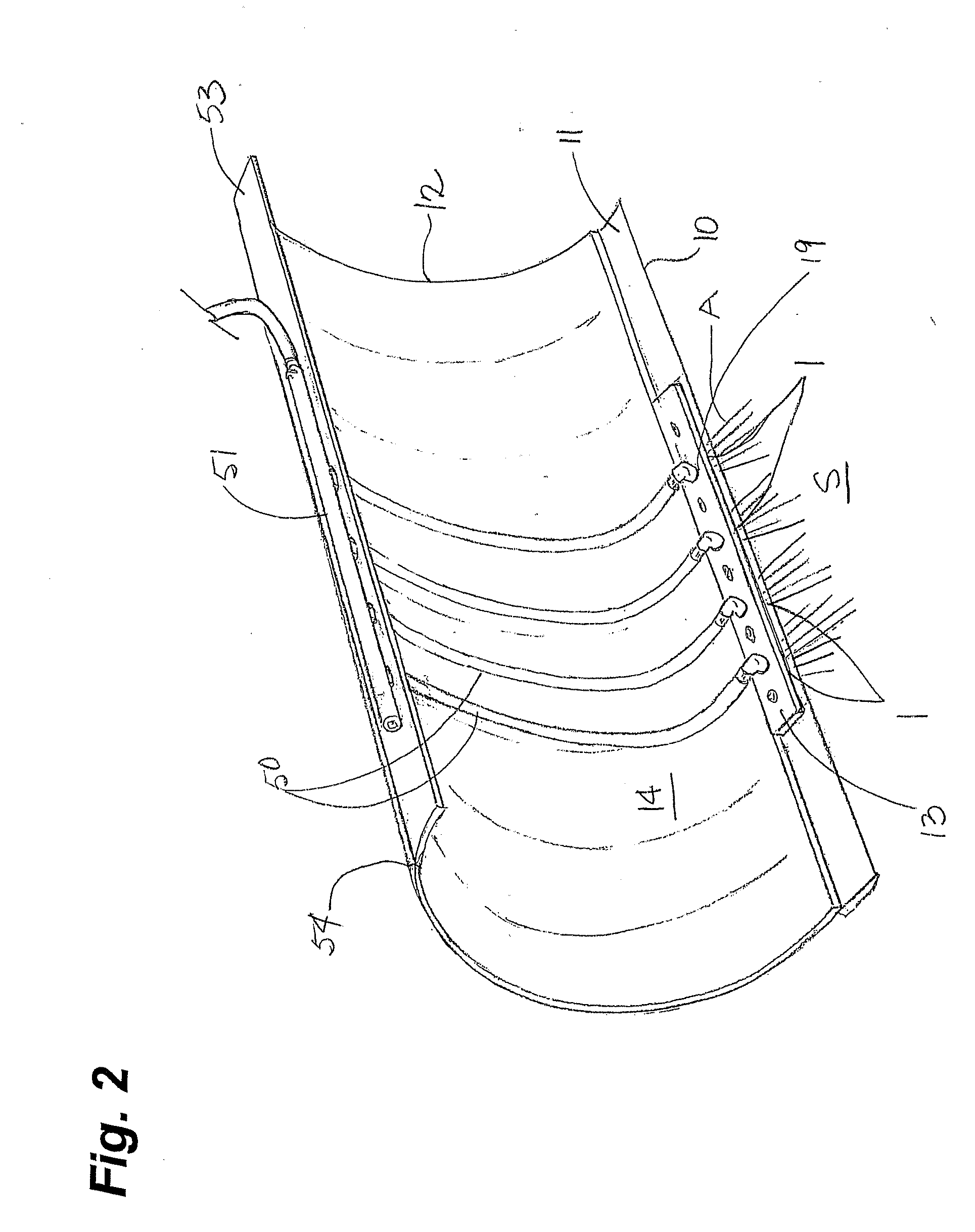
[0050] As shown in FIGS. 1 and 2, one or more substantially longitudinally extending nozzles 1 are formed above, or lagging, a leading edge 10 of a ground engagement tool (GET) 11 mounted on a conventional scraper blade 12 to direct substantially planar jets of air A at a surface S, such as a roadway, to reduce snow packing and ice formation and for removal of other debris therefrom. In embodiments of the invention, the substantially longitudinally extending nozzles 1 are oriented transversely to a direction of travel T of the nozzles 1. Typically therefore, in use on a snow plow, the nozzles 1 are mounted tran...
PUM
 Abstract
Description
Claims
Application Information