Wet electro-core gas particulate separator

Inactive Publication Date: 2007-01-02
ELECTRIC POWER RES INST INC
View PDF13 Cites 27 Cited by
  • Summary
  • Abstract
  • Description
  • Claims
  • Application Information

AI Technical Summary

Benefits of technology

[0020]A first object of the invention is to improve the operational effectiveness of gas separation systems. A second object of the invention is to reduce or eliminate down time required for cleaning or removing filtrate. A third object of the invention is to enhance existing cleaning techniques with a complementary and non-exclusive technique to obtain the benefits of both. Another object of the invention is to eliminate the need for a second effluent gas stream and also prevent

Problems solved by technology

These features and limitations have dictated application.
Unfortunately, flow through a filter is limited by the surface area and cleanliness of the filter, and the size of the openings in the filter.
In higher volume systems, in corrosive or extreme environments, and in environments with large quantities of fine particulate, filters tend to clog quickly and unpredictably, and present undesirable resistance to the passage of the gas stream.
During the period of filter changing or cleaning, which can be particularly tedious, the machine, equipment, or process must be stopped or diverted.
This shut-down requires either a duplicate filtration pathway, which may add substantial cost and space requirements, or a shut-down of the machine or process.
The limitations present design challenges that have primarily limited this technology to low volume purification.
Unfortunately, the liquid must also be processed, and where there are high levels of particulates, the particulates must be separated from the liquid by yet another process, or the liquid and particulates must be transported to some further industrial or commercial process or disposal location.
Similar to washing, flocculation necessitates the introduction of additional materials that add bulk to the waste stream and unnecessarily complicate the handling and disposal of the contaminants.
Furthermore, the flocculating materials must also be provided as raw materials, which may add substantial expense in the operation of such a device, Consequently, flocculation is normally reserved for systems and operations where other techniques have been unsuccessful, or where a particular material is to be removed from the gas stream wh

Method used


Image

  • Wet electro-core gas particulate separator
  • Wet electro-core gas particulate separator

Examples


Example

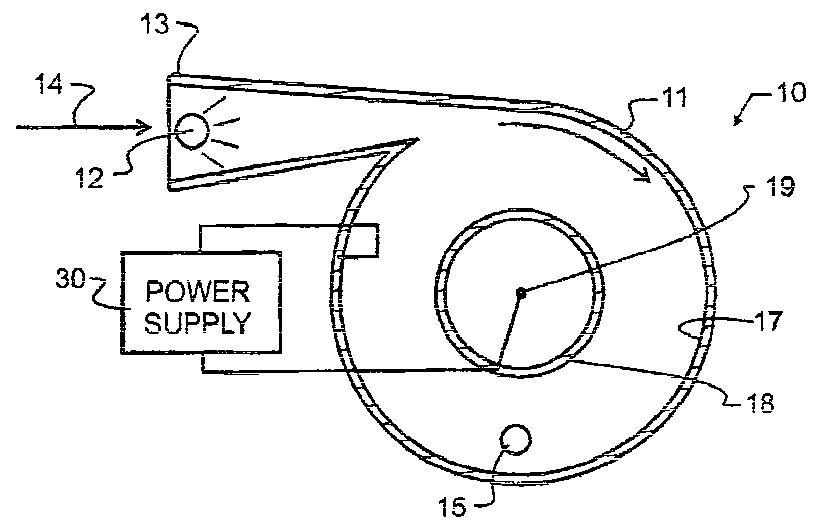
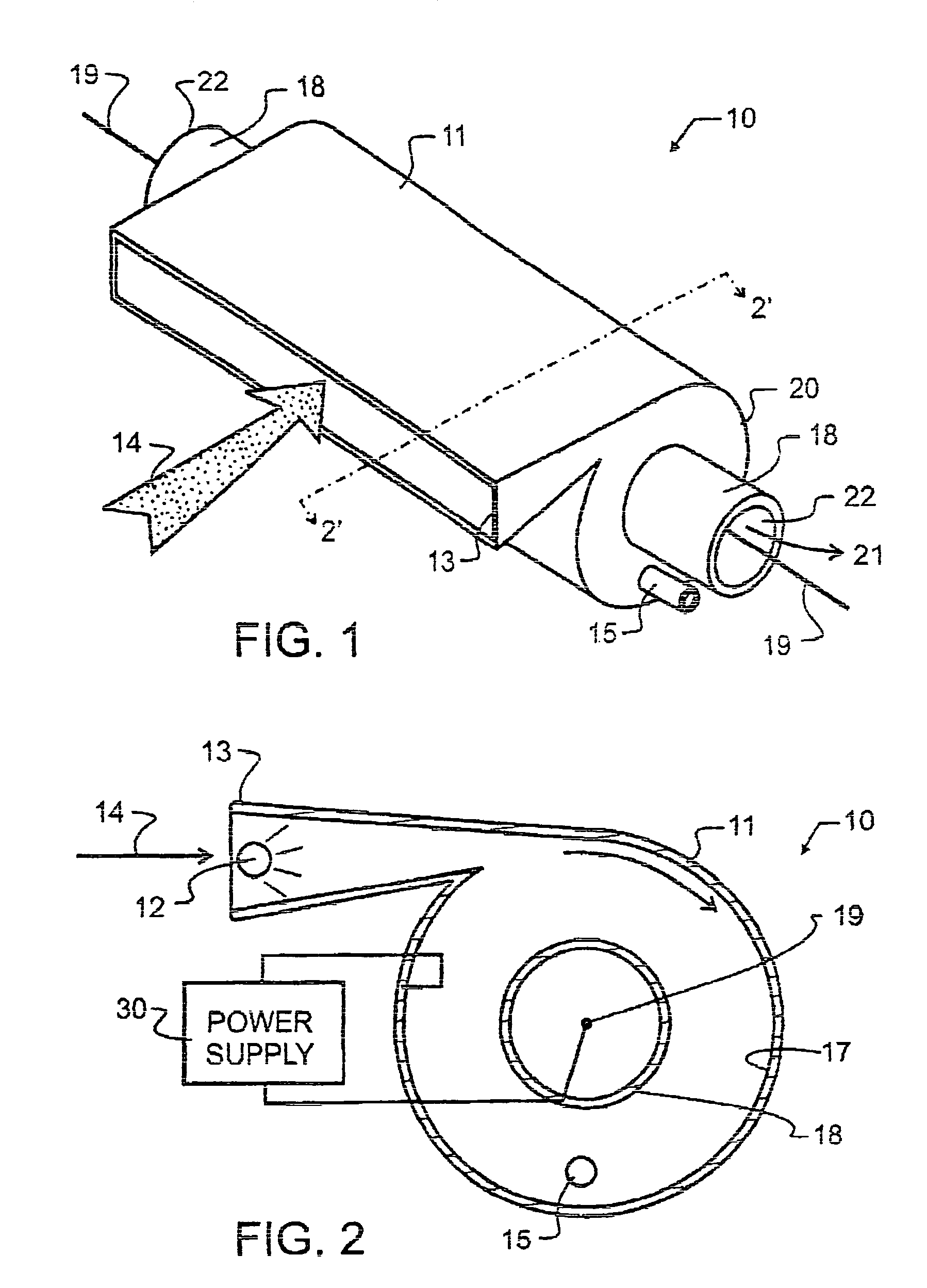
[0023]As illustrated in FIGS. 1 and 2, wet electro-core 10 includes a cylindrical separation vessel 11 having a triangular prism-shaped inlet passage 13 for admitting gas stream 14. While a number of other shapes besides the preferred triangular prism may be conceived for inlet passage 13, several desirable conditions should be met by the design. First, a means for introducing a mist or spray into gas stream 14, such as spray tube 12 illustrated in FIG. 2, will be provided. Most preferably, the induction of water droplets into gas stream 14 will be accomplished to minimize the separation of water from gas stream 14 and to prevent dripping or undesirable run-off from spray tube 12 within inlet passage 13. Where this dripping is not preventable, or as a preventative measure, drain means may be provided, and may, for exemplary purposes, couple into drain tube 15 described herein below. Most preferably, the droplets of water will be thoroughly admixed into gas stream 14 to provide a max...


PUM


Abstract

A gas separation apparatus combines the technologies of electrostatic precipitators and centrifugal particle separators into a single unit. At an inlet into the gas separation apparatus, a water spray is introduced into the gas stream. The water spray may include various chemical additives, typically selected to react with or neutralize the particulates as they are mixed with the water or for other benefit. The resulting water and particulate mixture, which is much more dense than air, is centrifugally separated and collected through a drain tube outlet. In addition to the centrifugal forces applied to the gas and water stream, an electrical field of magnitude sufficient to produce coronal discharge is also applied to a central electrode. The electric field is generated between the cylinder wall and the central electrode, to assist the centrifugal forces and thereby remove additional particulate beyond that ordinarily removed by a standard centrifugal separator. A vortex finder surrounds the central electrode and protects the electrode from undesirable exposure to water splashes or the like, while assisting with the centrifugal separation. The novel separation apparatus and technique offer particular synergy when applied to the effluent stream from a fossil-fuel electric power plant or other similar gas streams.

Description

BACKGROUND OF THE INVENTION[0001]1. Field of the Invention[0002]This invention pertains generally to gas separation apparatus, and more specifically, to the combination of wet centrifugal separation with electrostatic precipitation for the removal of fine particulate and gas contaminants from an air stream in a compact and essentially continuous process.[0003]2. Description of the Related Art[0004]Industries as diverse as mills, pharmaceutical, chemical, and food processing factories, and cement kilns must all separate contaminants or particulates from an air or gaseous stream. The gases may be a product of combustion, such as present in an exhaust stack, but may also represent other gas streams and may contain such diverse materials as liquid particulates, smoke or dust from various sources, and the like. Separators that must process relatively large volumes of gas are common in power generating facilities and factories.[0005]The techniques used for purification of gas streams have...

Claims


Application Information

Patent Timeline
IPC IPC(8): B03C3/013B03C3/014
CPCB03C3/014B03C3/366B03C3/16B03C3/15
Inventor ALTMAN, RALPH F.
Owner ELECTRIC POWER RES INST INC
Why Eureka
Try Eureka