
Method and system for removing contaminants from a surface

Inactive Publication Date: 2010-03-25
CARL ZEISS SMT GMBH
View PDF3 Cites 20 Cited by
  • Summary
  • Abstract
  • Description
  • Claims
  • Application Information

AI Technical Summary

Benefits of technology

[0019]It has been found that heating the contaminated surface enhances the cleaning effect of atomic hydrogen or deuterium. Even for pressures below 10−4 Torr, high cleaning rates can be achieved. Particularly high cleaning rates can be achieved for pressures over 10−3 Torr. In particular, it has been found that deuterium reacts with many contaminants, inter alia carbon contaminants or metal contaminants to volatile compounds.

Problems solved by technology

The surface damage due to contamination by hydrocarbons reduces the reflectance of each reflective optical element.

Method used


Image

  • Method and system for removing contaminants from a surface
  • Method and system for removing contaminants from a surface
  • Method and system for removing contaminants from a surface

Examples


example 1

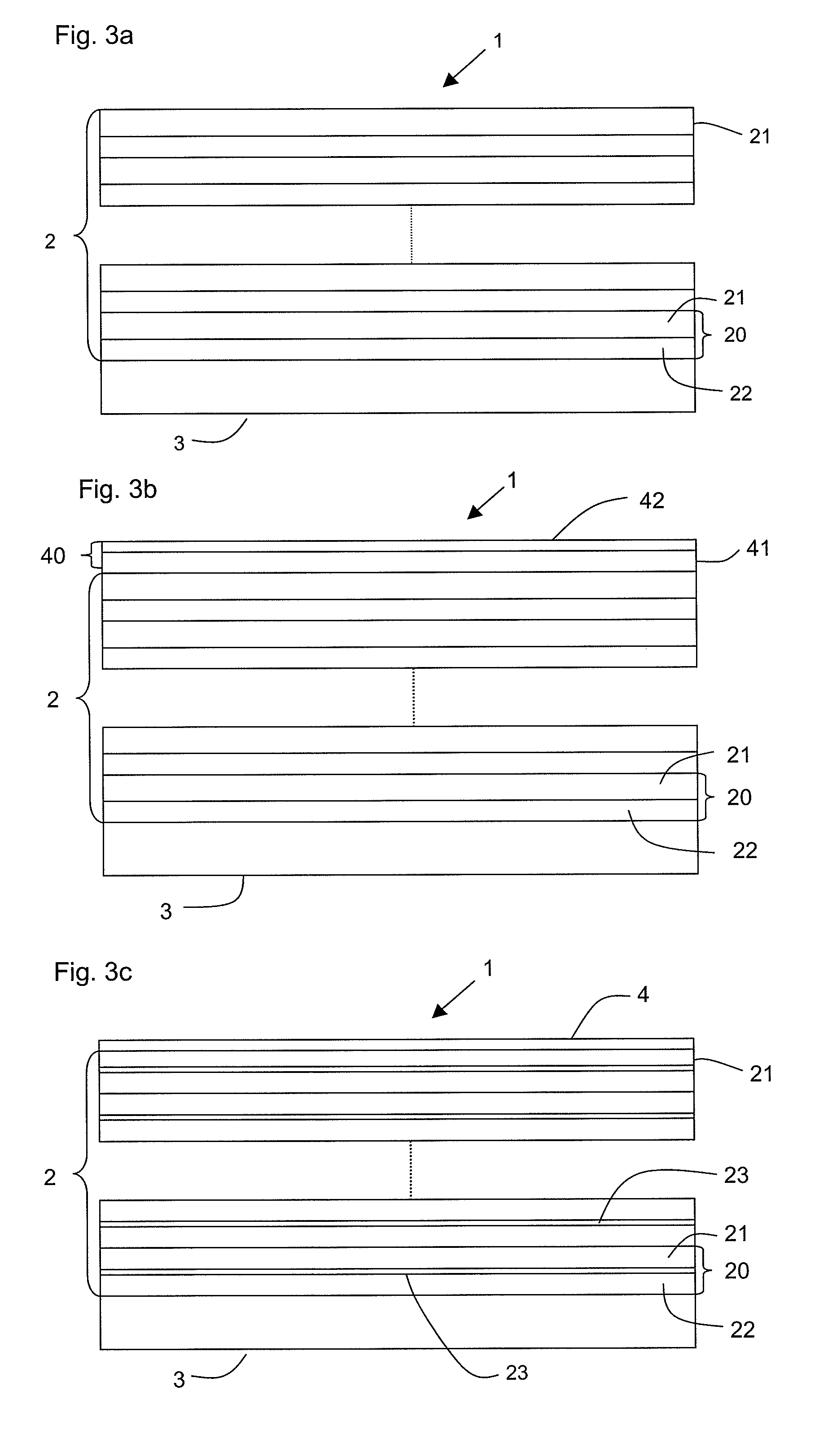
[0049]A molybdenum / silicon multilayer mirror with a capping system with a silicon nitride layer and a ruthenium layer has been heated to around 55° C. to 60° C. during 2.5 hours while atomic hydrogen was injected at a pressure of ca. 0.03 Torr at a flow of 1000 sccm and passing a hot filament of a temperature of ca. 1800° C., and a cleaning rate of 1.2 Å / h was achieved.

example 2

[0050]A molybdenum carbide / silicon multilayer mirror with barrier layers of silicon boride has been heated to around 100° C. during 2.5 hours while atomic deuterium was injected at a pressure of ca. 0.03 Torr at a flow of 1000 sccm and passing a hot filament of a temperature of ca. 2000° C., and a cleaning rate of 3.5 Å / h was achieved.

example 3

[0051]A molybdenum / beryllium multilayer mirror with barrier layers of boron carbide and with a rhodium capping layer has been heated to around 200° C. during 2 hours while atomic hydrogen was injected at a pressure of ca. 0.03 Torr at a flow of 2000 sccm and passing a hot filament of a temperature of ca. 2000° C., and a cleaning rate of 13 Å / h was achieved.


PUM

PropertyMeasurementUnit
Temperatureaaaaaaaaaa
Pressureaaaaaaaaaa

Abstract

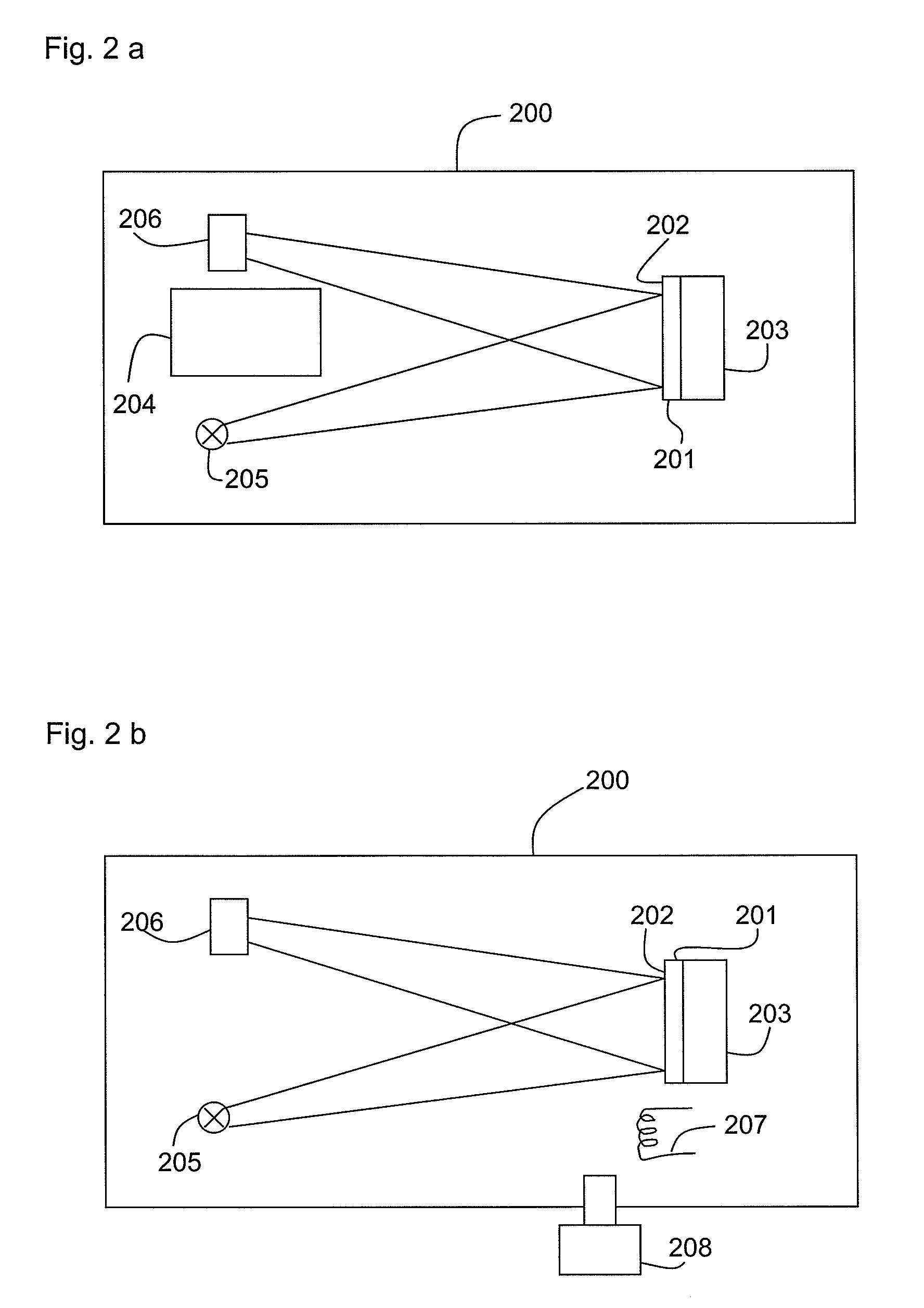
Inside a vacuum chamber 200 a cleaning unit 204 provides atomic hydrogen or atomic deuterium for cleaning a surface 202 at a pressure of less than 10−4 Torr or of more than 10−3 Torr. The surface 202 is heated by the heating unit 203 to a temperature of at least 50° C. This allows achieving cleaning rates of more than 60 Å / h. Preferably, the surface 202 is the surface of a multilayer mirror 201 as used in an EUV lithography apparatus.

Description

FIELD OF THE INVENTION [0001]The present invention relates to methods for removing contaminants from a surface. The present invention further relates to method for removing contaminants from a surface inside an EUV lithography apparatus. In addition, the present invention relates to a system for removing contaminants from a surface.BACKGROUND AND RELATED ART [0002]Extreme ultraviolet (EUV) lithography apparatuses, i.e. lithography apparatuses working in an extreme ultraviolet wavelength range of approximately 1 nm to 20 nm, are mainly used for the production of semiconductor devices. For the illumination of a reticle and the projection of the reticle's structure onto e.g. a wafer, in particular reflective optical elements are utilized. During operation, the reflective optical elements in an EUV lithography apparatus are exposed to a radiation of up to 20 mW / mm2 EUV photon density or more and to residual gases such as hydrocarbons, water, hydrogen, oxygen or others. The residual gase...

Claims


Application Information

Patent Timeline
IPC IPC(8): B08B5/04B08B7/00C03C25/70
CPCB08B7/00G03F7/70925B08B7/0071
Inventor EHM, DIRK HEINRICHSCHMIDT, STEFANKRAUS, DIETERWIESNER, STEFANKOEHLER, STEFANCZAP, ALMUTCHUNG, HIN YIU ANTHONY
Owner CARL ZEISS SMT GMBH
Learn More