Pole joint screw for a basketball goal system

a technology of basketball goal and screw, which is applied in the direction of screws, fastening means, rod connections, etc., can solve the problems of screw design, inability to unintentionally release or remove, and difficulty or impossible to access both sides of the fastener

Inactive Publication Date: 2006-02-07
LIFETIME PRODUCTS
View PDF7 Cites 18 Cited by
  • Summary
  • Abstract
  • Description
  • Claims
  • Application Information

AI Technical Summary

Benefits of technology

[0011]A need therefore exists for a fastener for a basketball system that eliminates the above-described disadvantages and problems.

Problems solved by technology

Desirably, the fastener allows two elongated or enlarged structures to be connected in which it is difficult or impossible to access both sides of the fastener.
That is, the screw is designed such that it cannot be unintentionally released or removed.

Method used


Image

  • Pole joint screw for a basketball goal system
  • Pole joint screw for a basketball goal system

Examples


Embodiment Construction

[0025]The present invention is directed towards a pole joint screw for use in connection with a support pole for a basketball system. The principles of the present invention, however, are not limited to a pole joint screw for use in connection with a support pole for a basketball system. It will be understood that, in light of the present disclosure, the pole joint screw disclosed herein can be successfully used in connection with other types of sporting equipment and devices.

[0026]Additionally, to assist in the description of the pole joint screw, words such as top, bottom, front, rear, right and left are used to describe the accompanying figures. It will be appreciated, however, that the present invention can be located in a variety of desired positions—including various angles, sideways and even upside down. A detailed description of the pole joint screw now follows.

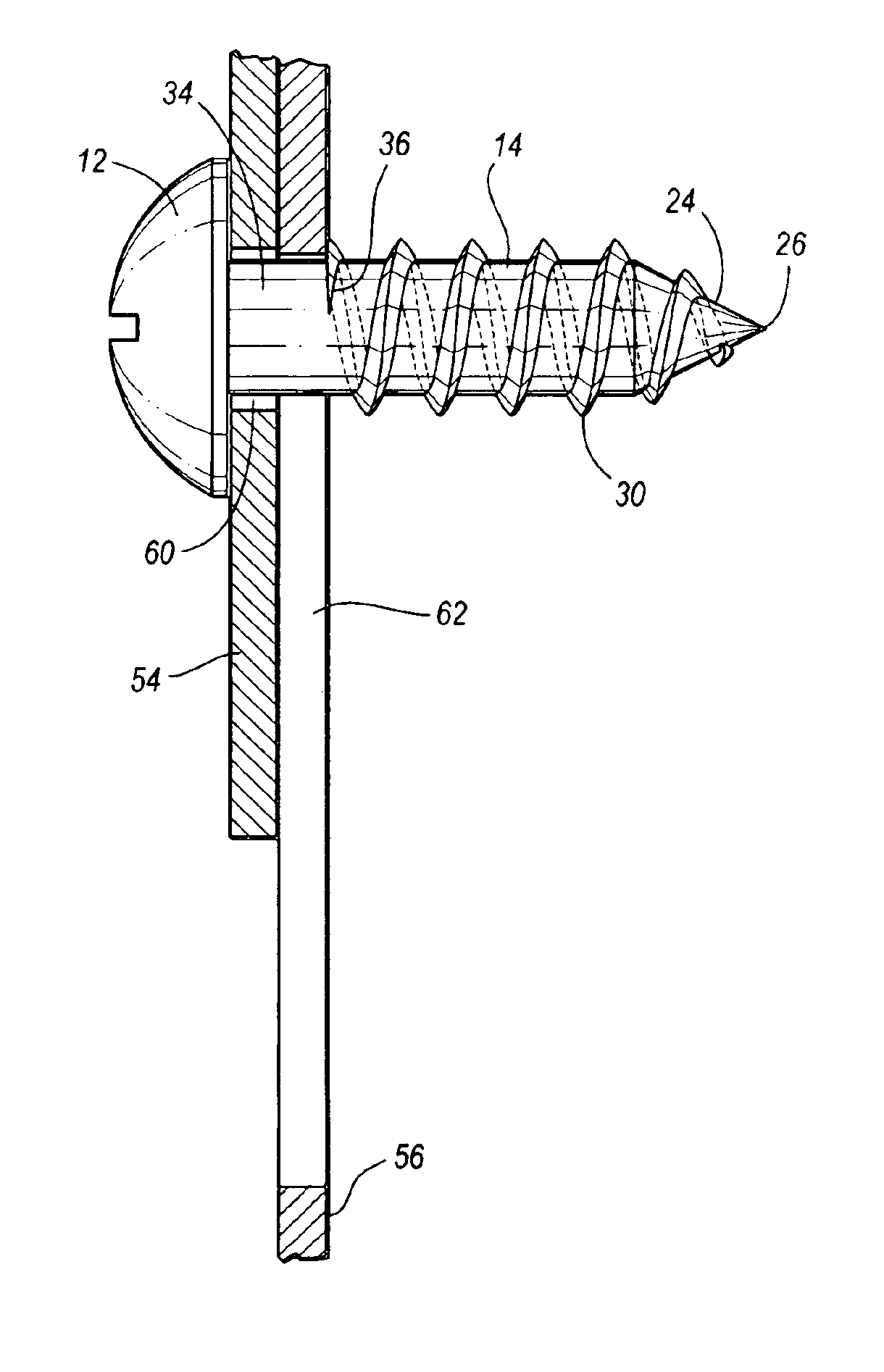
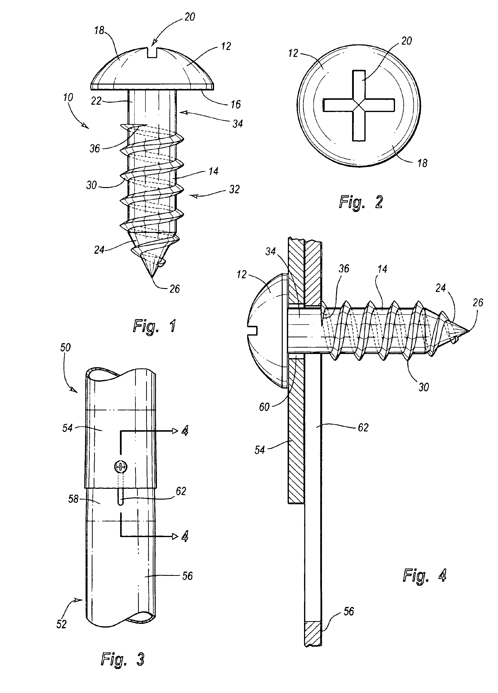
[0027]As seen in FIG. 1, the pole joint screw 10 includes a head 12 and a body 14. The head 12 includes a first end...


PUM


Abstract

A pole joint screw may be used to connect a first section of a basketball support pole and a second section of a basketball support pole. The pole joint screw may include an elongated body including a first end and a second end, a head disposed on the first end of the elongated body, a threaded portion disposed on the second end of the elongated body, and a gap disposed between the head and the threaded portion. The gap is preferably sized and configured to receive a portion of the first section of the basketball support pole and a portion of the second section of the basketball support pole. The pole joint screw preferably freely rotates when the portion of the first section of the basketball support pole and the portion of the second section of the basketball support pole are located in the gap.

Description

CROSS-REFERENCE TO RELATED APPLICATIONS[0001]This application claims priority to and the benefit of U.S. Provisional Patent Application Ser. No. 60 / 403,742, entitled Pole Joint Screw for a Basketball Goal System, which was filed on Aug. 14, 2002, and is hereby incorporated by reference in its entirety.BACKGROUND OF THE INVENTION[0002]Field of the Invention[0003]Many types of fasteners are commonly used to connect two or more components or structures. For example, permanent fasteners such as rivets and weldments may be used to permanently connect two or more components or structures. Advantageously, rivets can provide secure connection of many types of components or structures, whether the rivets are axially loaded or eccentrically loaded. Rivets, which include a cylindrical body known as a shank and a rounded end called the head, can be attached by inserting the shank through holes drilled or punched through the components or structures. The rivets can then be fastened by either a h...

Claims


Application Information

Patent Timeline
Patent Type & Authority Patents(United States)
IPC IPC(8): F16B35/04F16B7/10F16B25/00
CPCF16B35/048F16B7/10F16B25/00
Inventor WINTER, DAVID C.STEED, BRENT
Owner LIFETIME PRODUCTS
Why Eureka
Try Eureka