Method of determining static pressure in a ducted air delivery system using a variable speed blower motor

a ducted air delivery system and variable speed technology, applied in ventilation systems, lighting and heating apparatus, heating types, etc., can solve the problems of inefficient bypass and dump zones, no one hvac duct system is usually optimally efficient for every structure, and expensive and time-consuming processes. achieve the effect of efficient model of calculating static air pressur

Active Publication Date: 2006-02-07
CARRIER CORP
View PDF4 Cites 95 Cited by
  • Summary
  • Abstract
  • Description
  • Claims
  • Application Information

AI Technical Summary

Benefits of technology

[0016]According to a further aspect of the invention, control of the operation of an HVAC system by...

Problems solved by technology

Part of designing an efficient HVAC system entails properly balancing airflow, so that pressure differences at different points in the HVAC ducts do not create undesirable situations, such as, for example, cooling or heating one particular area of an environment without adequately cooling or heating another area.
Inefficient bypass and dump zones often are provided in zoning applications to regulate the air delivery when available airflow is too gre...

Method used


Image

  • Method of determining static pressure in a ducted air delivery system using a variable speed blower motor
  • Method of determining static pressure in a ducted air delivery system using a variable speed blower motor
  • Method of determining static pressure in a ducted air delivery system using a variable speed blower motor

Examples


Embodiment Construction

[0019]It is to be understood that the invention is not limited in its application to the details of construction and arrangements of components set forth herein in the detailed description of the preferred embodiment or illustrated in the drawings. The invention is capable of other embodiments and of being practiced or being carried out in various ways.

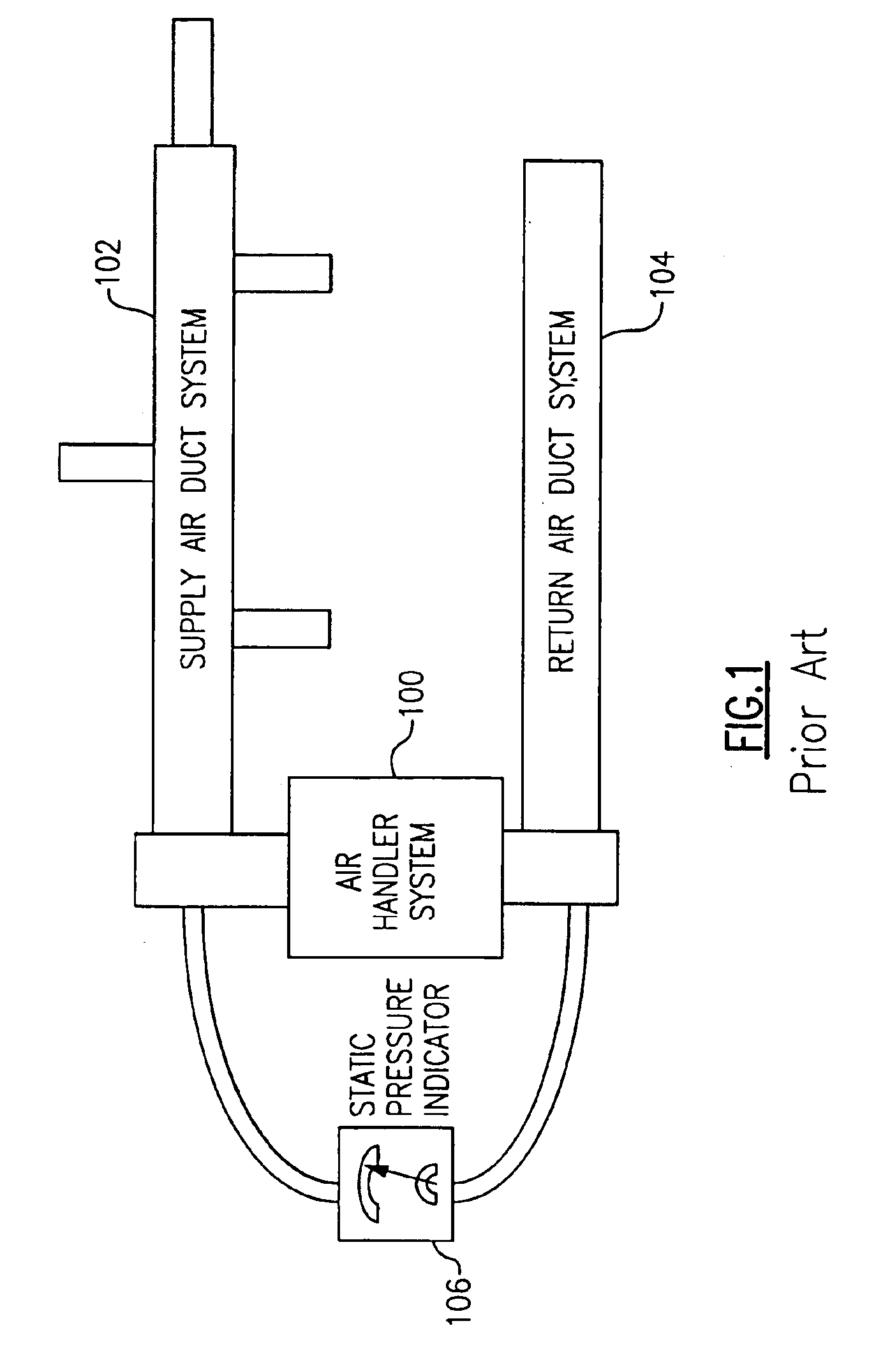
[0020]FIG. 1 describes, at a high-level, a typical HVAC system. Referring to FIG. 1, such a system employs a supply air duct system 102, a return air duct system 104, and an air handler system 100. The prior art system also employs one or more static pressure measurement / indicator devices, represented as instrument 106 in FIG. 1, to ascertain the static pressure of air moving through the system. As discussed above, such instruments are undesirable as requiring human participation and, often, special installation.

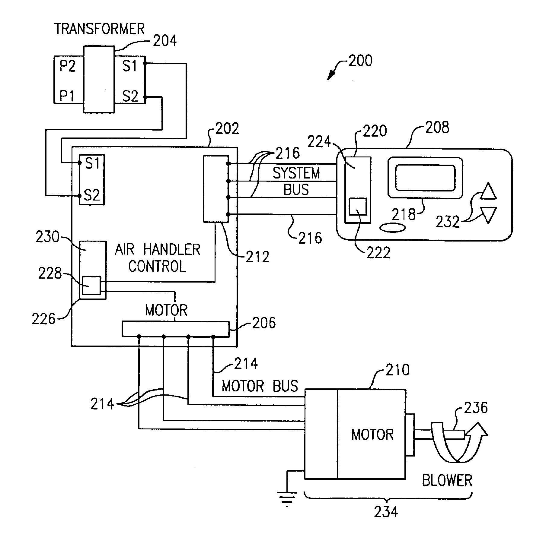
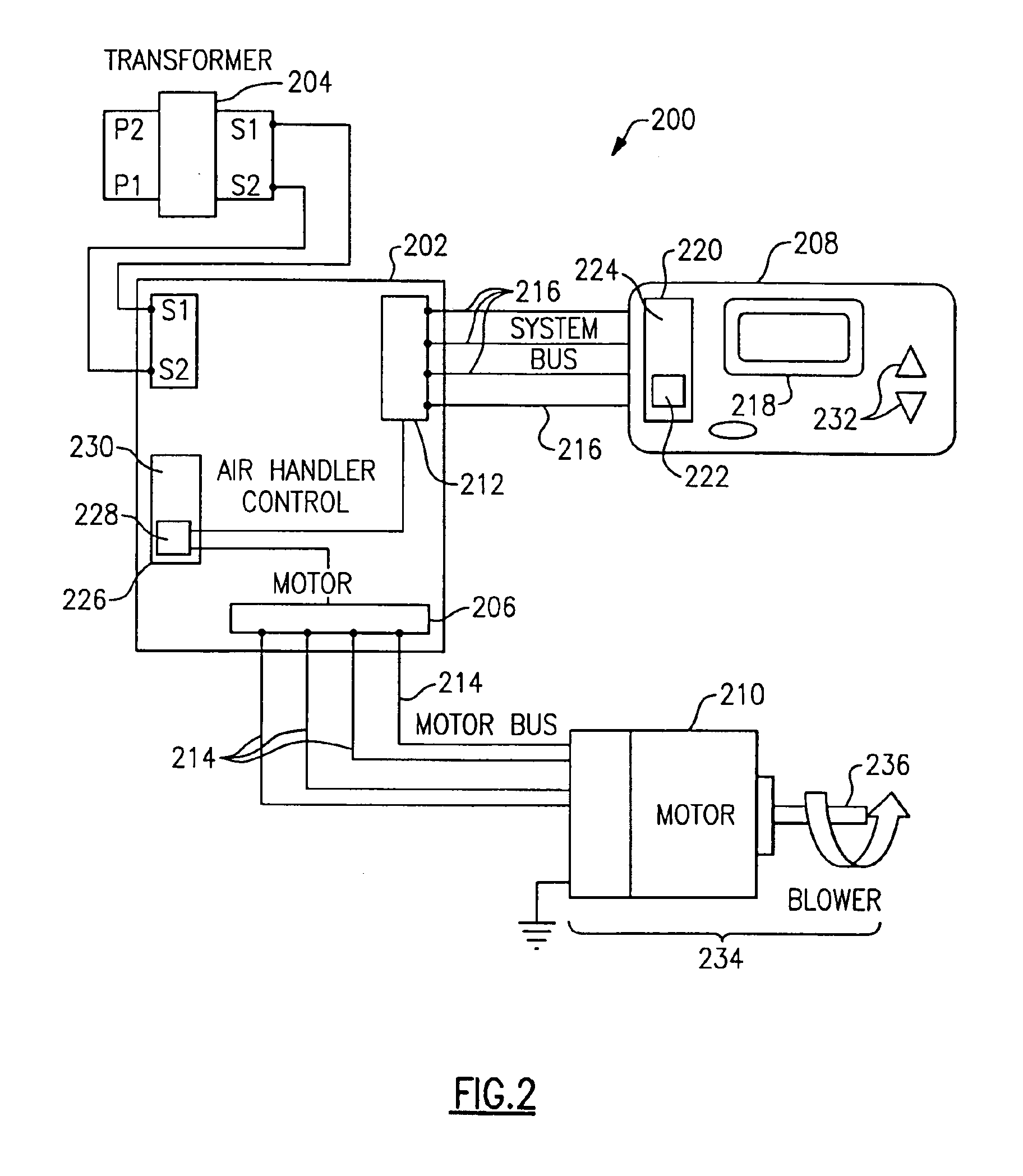
[0021]FIG. 2 illustrates an HVAC system 200 constructed in accordance with the present invention. Referring to FIG. 2, the H...


PUM


Abstract

Systems and methods of determining static air pressure in an HVAC system are provided. Static air pressure is mathematically determined as a function of system parameters, such as blower speed, blower diameter, system volume airflow rate, and/or blower motor torque. The determined static pressure can be used during HVAC installation and during HVAC monitoring and maintenance.

Description

CROSS REFERENCE TO RELATED APPLICATIONS[0001]None.[0002]1. Field of the Invention[0003]The invention relates generally to systems for, and methods of, precisely determining static fluid pressure, such as that of air, in a conduit system, such as a ducted air delivery system.[0004]2. Background of the Invention[0005]Modern structures, such as office buildings, manufacturing plants, barns, and residences, often are designed and constructed so as to allow control over environmental conditions within the structures. By way of example, environmental conditions such as temperature, humidity, air purity, air flow, enthalpy (combined value of temperature and humidity), and “fresh air” ventilation can be regulated to ensure that the interior environment of a structure is as may be desired for particular occupants and equipment housed in the structure, and for processes and procedures conducted within the structure.[0006]In practice, one typical way of regulating environmental conditions with...

Claims


Application Information

Patent Timeline
IPC IPC(8): F24F11/00F24F11/75
CPCF24F11/006F24F11/047F24F2011/0042F24F11/30F24F2110/40F24F11/62F24F11/75F24F11/74
Inventor MILLS, EUGENE L.
Owner CARRIER CORP
Why Eureka
Try Eureka