Image forming apparatus

Inactive Publication Date: 2006-02-07
CANON KK
View PDF11 Cites 3 Cited by
  • Summary
  • Abstract
  • Description
  • Claims
  • Application Information

AI Technical Summary

Benefits of technology

[0011]The primary object of the present invention is to provide an image forming apparatus satisfactory in terms of both apparatus cost and productivity.
[0012]Another object of the pre

Problems solved by technology

Developer is in the form of extremely small particulates, creating therefore the problem that when an operator supplies the image forming apparatus with developer, developer scatters, contaminating the adjacencies thereof.
In the case of this type of method, it is rather difficult to automatically discharge the developer using only the natural force, more specifically, gravity.
The above described developer supply containers in accordance with the prior art, however, had the following problems.
In other words, it is greater in component count, being higher in cost.
This adds to the cost of a developer supply container.
Thus, in consideration of the fact that the rotary developing apparatus in accordance with the prior art comprises a plurality of interchangeably structured developer supply containers, and also a plurality of interchangeably structured develop

Method used


Image

  • Image forming apparatus
  • Image forming apparatus
  • Image forming apparatus

Examples


embodiment 1

(Embodiment 1)

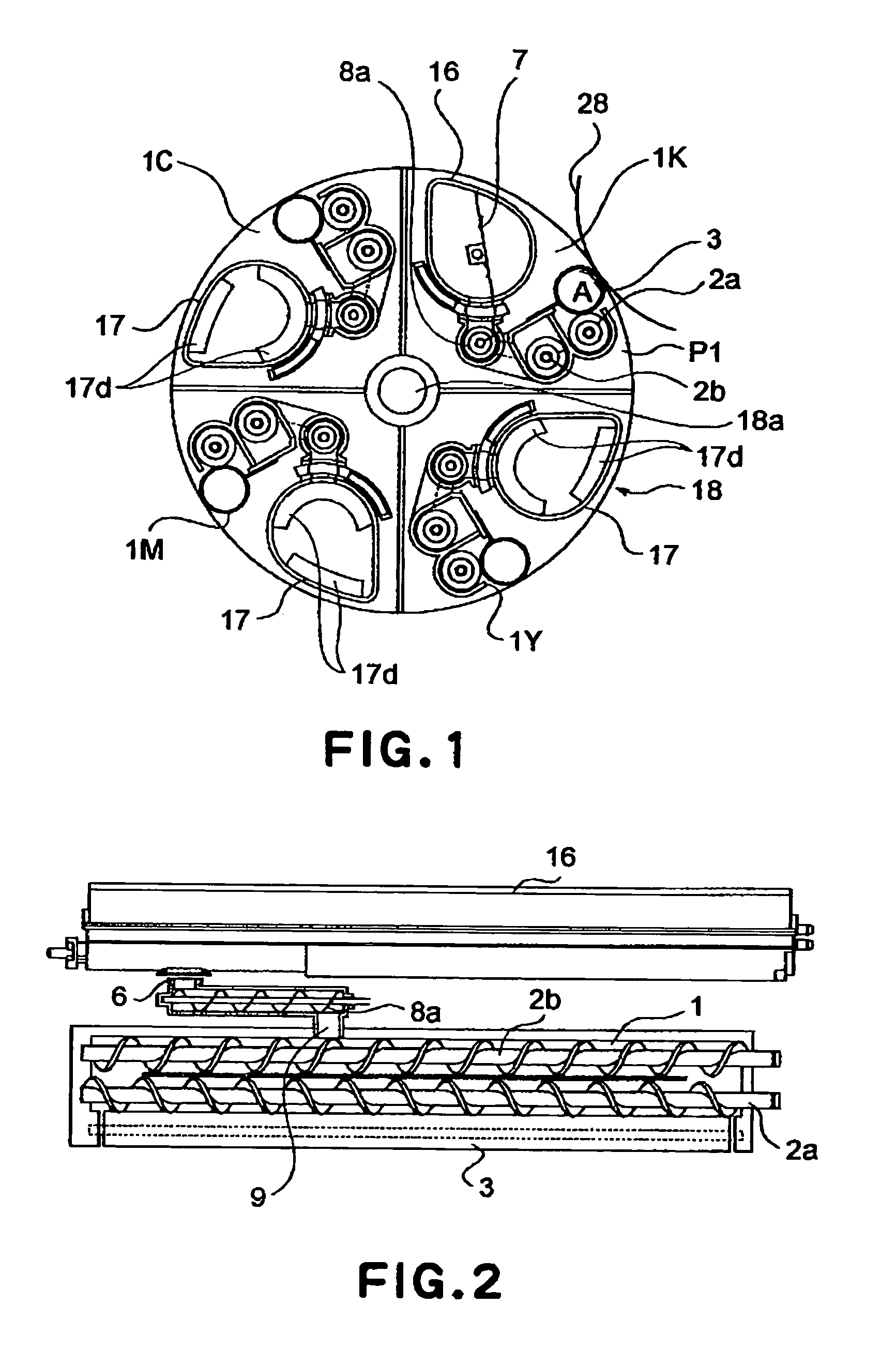
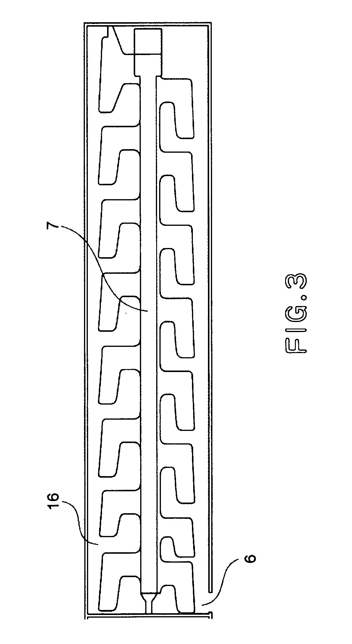
[0034]Hereinafter, referring to FIGS. 1–5, the first embodiment of the present invention will be described. FIG. 1 is a lengthwise sectional view of the developing apparatus in the first embodiment of the present invention, and FIG. 2 is a cross-sectional view of the developing device in the first embodiment. FIG. 3 is a lengthwise sectional view of the developer supply container having an internal member for conveying the developer in the container while stirring the developer, in the first embodiment, and FIG. 4 is a plan view of the inward sides of the top and bottom halves of the developing supply container, in the first embodiment of the present invention, having no developer stirring-conveying internal member, as seen from the directions toward which the molds therefor are removed. FIG. 5 is a perspective view of the inward sides of the top and bottom halves of the developer supply container, in the first embodiment of the present invention, having no developer s...

embodiment 2

(Embodiment 2)

[0046]Next, referring to FIGS. 6 and 7, the second embodiment of the present invention will be described. FIG. 6 is a cross-sectional view of the developing apparatus in the second embodiment of the present invention, and FIG. 7 is a lengthwise sectional view of the developer supply container, in the second embodiment, having an internal developer stirring-conveying member.

[0047]This embodiment is similar in many respects to the first embodiment. Therefore, it will be described regarding only the characteristic aspects thereof.

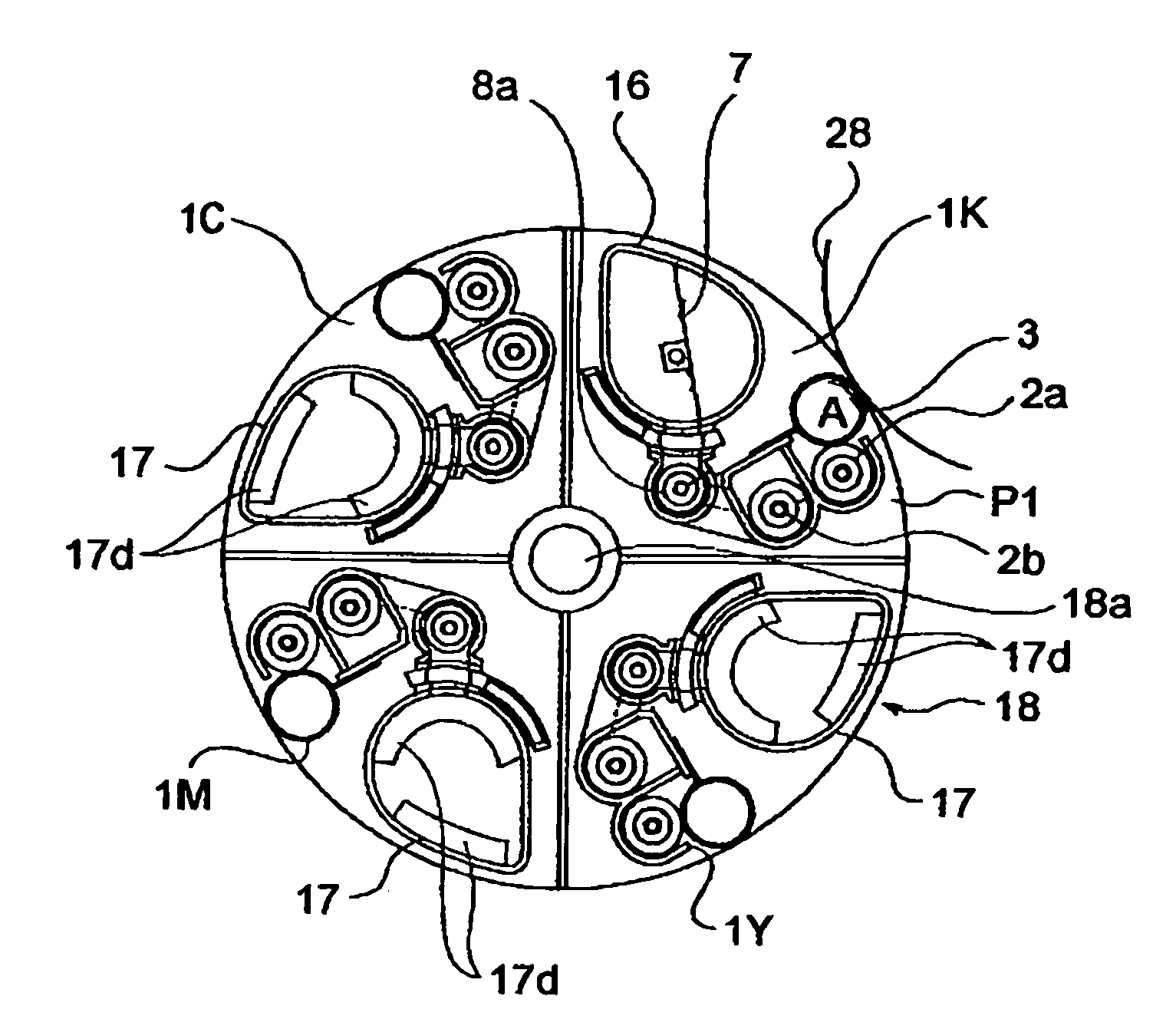
[0048]First, the image forming apparatus compatible with the rotary developing apparatus in this embodiment will be described. Referring to FIG. 1, a rotary 18 holds a plurality of developing devices 1K, 1Y, 1M, and 1C, and can be rotated by rotationally driving the center shaft 18a of the rotary 18 by an unshown motor. In order to form a black toner image on the photosensitive drum 28, the rotary 18 is rotated to move the developing device 1K in...


PUM


Abstract

An image forming apparatus includes a first developing device and a second developing device for developing an electrostatic latent image formed on an image bearing member and a developing portion; a rotatable member supporting the first and second developing devices, the rotatable member being rotatable along a path through the developing portion; a first developer supply container and a second developer supply container, supported on the rotatable member, for supplying developer into the first developing device and into the second developing device; wherein the developer in the first developer supply container is fed using rotation of the rotatable member, whereas the developer in the second developer supply container is fed without using rotation of the rotatable member.

Description

FIELD OF THE INVENTION AND RELATED ART[0001]The present invention relates to an image forming apparatus employing an electrophotographic, electrostatic, or the like recording method. In particular, it relates to such an image forming apparatus as a copying machine, a printer, a facsimile machine, and a multifunction image forming apparatus capable of performing two or more of the functions of the preceding apparatuses.[0002]Developer in the form of particulates has long been used as the developer for an image forming apparatus such as an electrophotographic copying machine, a printer, etc. As the amount of the developer in the main assembly of an image forming apparatus is reduced to a critical level by consumption, a developer supply container is used to supply the image forming apparatus with developer. Developer is in the form of extremely small particulates, creating therefore the problem that when an operator supplies the image forming apparatus with developer, developer scatte...

Claims


Application Information

Patent Timeline
IPC IPC(8): G03G15/01G03G15/06G03G15/00G03G15/08
CPCG03G15/0126G03G15/0173G03G15/0121G03G2215/0177A01K97/10Y10S269/907Y10S81/01
Inventor AWAYA, TETSURO
Owner CANON KK
Why Eureka
Try Eureka