Image recording apparatus and recording-material feeding method

a technology of image recording apparatus and recording material, which is applied in the direction of recording apparatus, printing equipment, instruments, etc., can solve the problems of complex mechanism, affecting the quality of photo prints, and causing load fluctuation, so as to prevent scanning unevenness, prevent scanning unevenness, and facilitate control

Inactive Publication Date: 2005-08-25
FUJIFILM HLDG CORP +1
View PDF3 Cites 1 Cited by
  • Summary
  • Abstract
  • Description
  • Claims
  • Application Information

AI Technical Summary

Benefits of technology

[0017] In the image recording apparatus according to the present invention, it is unnecessary to independently nip and release the recording materials at the respective rows. As a result, it is possible without complicating a structure to prevent scanning unevenness from occurring at the time of simultaneous exposure of the recording materials. Moreover, it is possible to prevent the scanning unevenness from occurring due to slight vibration to be caused on the adjacent row at the time of nipping and releasing. Thus, control may be easily conducted. As a result, manufacturing cost of the apparatus may be held down.
[0018] Since the position adjuster is provide, it is possible to take the balance of nipping by adjusting the positions of the recording materials in a scanning direction even when the recording materials fed in parallel have different widths.
[0019] The image recording positions of the recording material are adapted to be staggered so that the roller causing the scanning unevenness is easily identified.
[0020] By the recording-material feeding method according to the present invention, it is similarly possible without complicating the structure to prevent the scanning unevenness from occurring at the time of the simultaneous exposure.

Problems solved by technology

When an anterior end of the photosensitive material butts against a feed-roller pair and a posterior end thereof leaves from the feed-roller pair, load fluctuation is caused by a shock at that time.
Due to this, scanning unevenness occurs so that the quality of the photo print remarkably deteriorates.
However, since the feed-roller pairs are independently changed between the nip state and the release state, a mechanism thereof becomes complicated.
Thus, control becomes complicated.
Further, when the nip timing and the release timing of the adjacent feed-roller pairs are different, load fluctuation is caused.
As a result, scanning unevenness occurs relative to the adjacent rows.
In addition, when the photosensitive material has a wide width so as to overlap with the plural feed-roller pairs, load fluctuation is caused in case the nip timing and the release timing are not properly set relative to the adjacent feed-roller pairs.
In this case, the scanning unevenness is likely to occur.

Method used


Image

  • Image recording apparatus and recording-material feeding method
  • Image recording apparatus and recording-material feeding method
  • Image recording apparatus and recording-material feeding method

Examples


Embodiment Construction

)

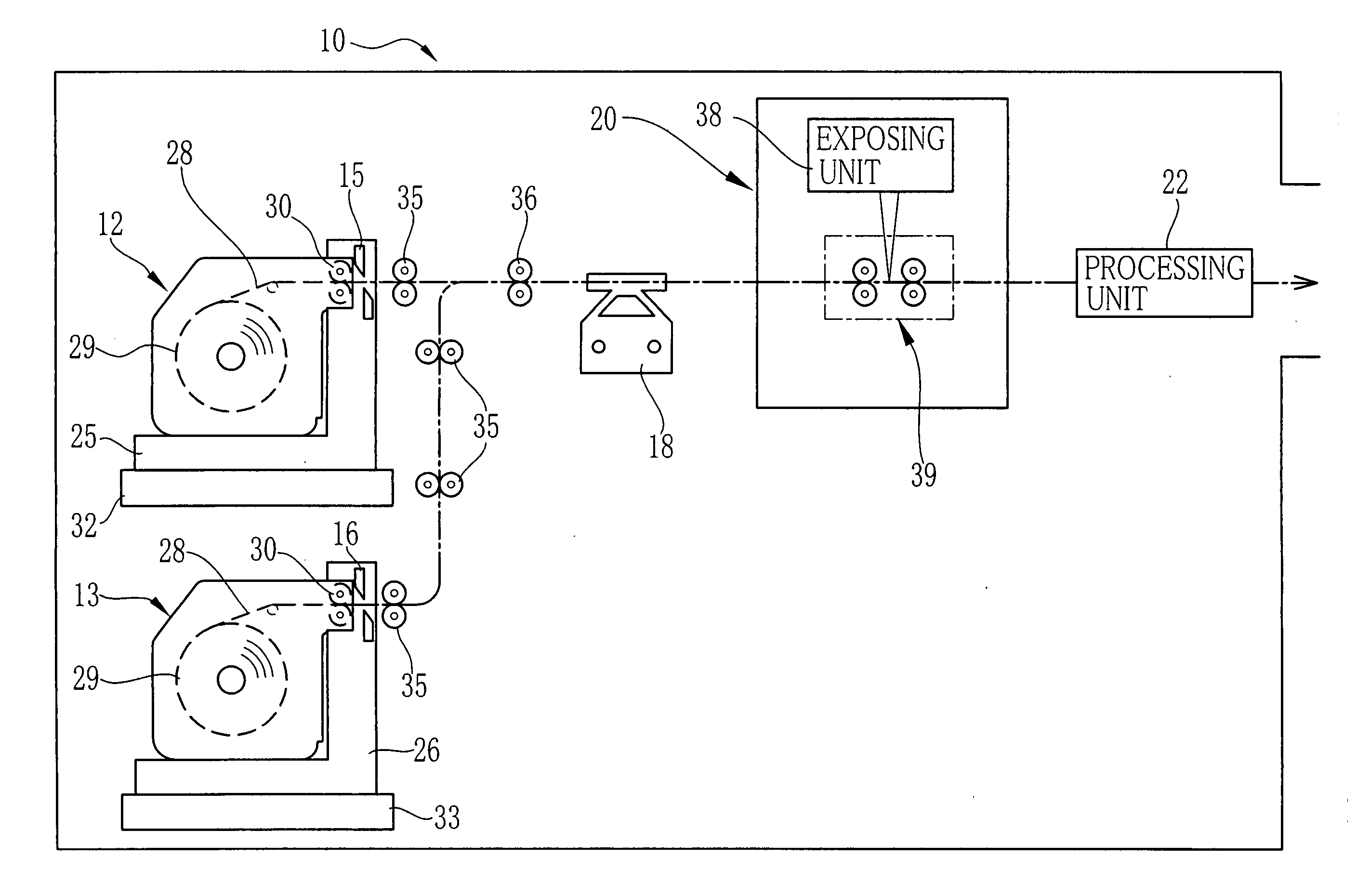
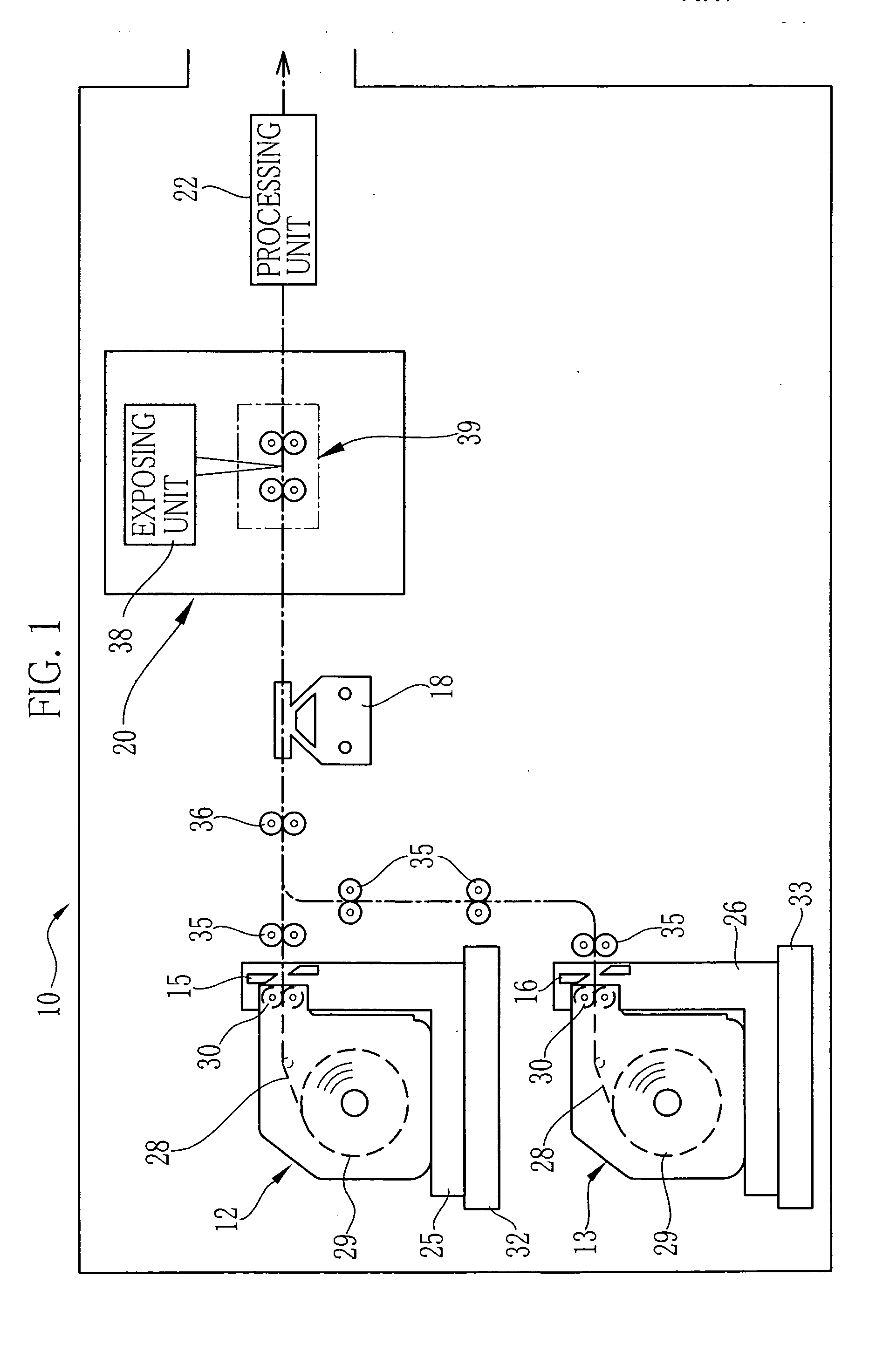
[0040]FIG. 1 is a schematic illustration showing a photographic printer 10 according to the present invention. In this printer 10, cut-sheet-shaped photosensitive materials of two rows are fed and simultaneously exposed. The exposed photosensitive material is outputted as a photo print. As shown in FIG. 1, the photographic printer 10 is constituted of magazines 12 and 13, cutters 15 and 16, a back-printing unit 18, an exposure section 20, a processing unit 22, and so forth.

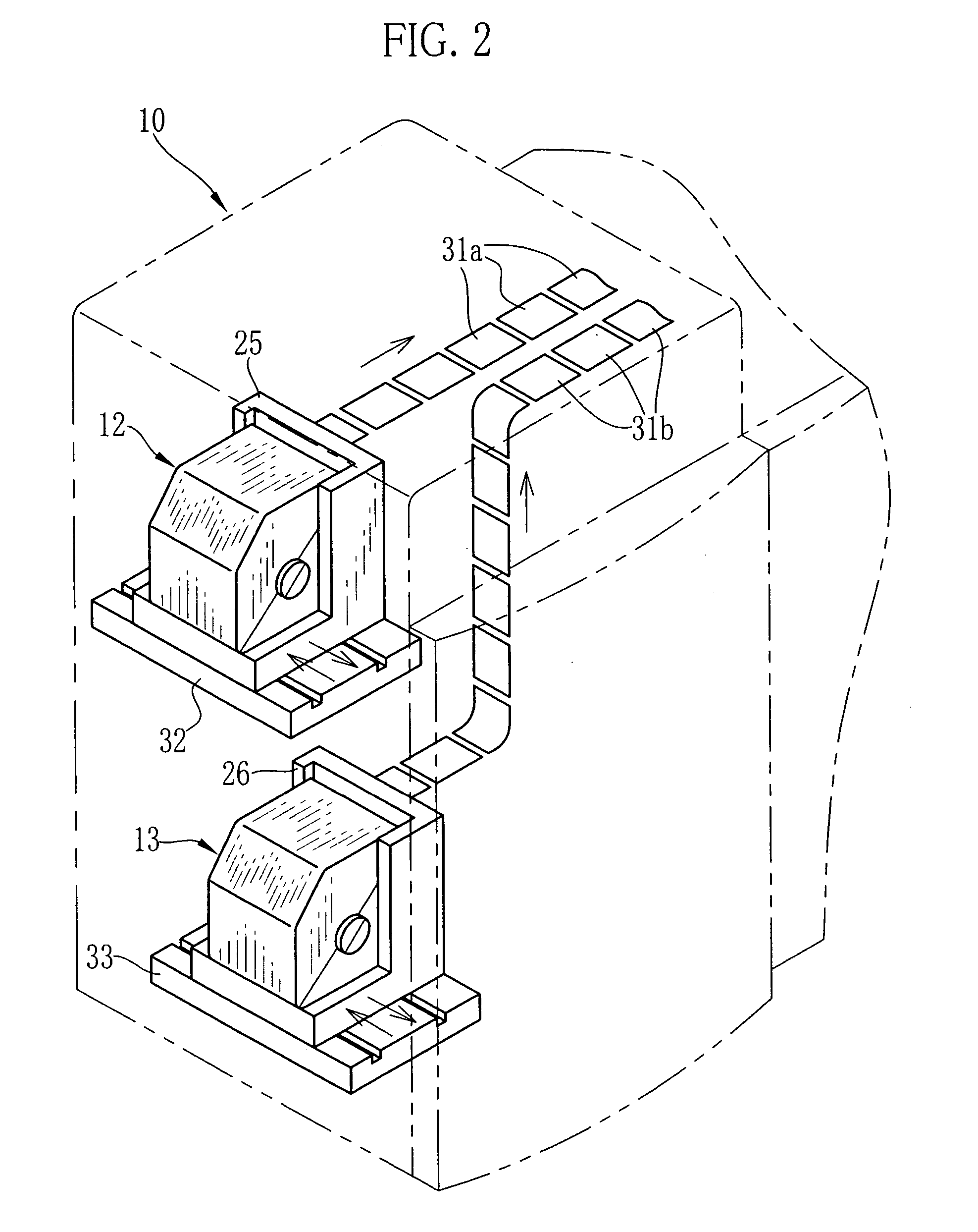
[0041] The magazines 12 and 13 are set to magazine stands 25 and 26 vertically disposed in parallel. Each of the magazines 25 and 26 contains a recording-paper roll 29 formed by rolling a strip of a photosensitive recording paper 28 being as a photosensitive material. A paper roller pair 30 is disposed near a paper mouth of the respective magazines 12 and 13. Upon rotating the paper roller pair 30 by means of a motor, which is not shown, the recording paper 28 is drawn out of the recording-paper roll 29 and is a...


PUM


Abstract

A feeder is provided inside an exposure section of a photographic printer. First and second feed-roller pairs are respectively disposed at an upstream side and a downstream side of an exposing position of the feeder. A first nip roller of the first feed-roller pair and a second nip roller of the second feed-roller pair are movable between a nip position for nipping paper sheets, and a release position for releasing the nip thereof. The second nip roller is moved to the nip position after an anterior end of the paper sheet situated at the most upstream side has passed the second nip roller. The first nip roller is moved to the release position before a posterior end of the paper sheet situated at the most downstream side leaves the first nip roller.

Description

BACKGROUND OF THE INVENTION [0001] 1. Field of the Invention [0002] The present invention relates to a method for feeding cut-sheet-shaped recording materials carried in parallel, and further relates to an image recording apparatus applying this feeding method. [0003] 2. Description of the Related Art [0004] For example, in a photographic printer, an image is recorded by so-called scanning exposure. In this photographic printer, while a photosensitive material of a cut-sheet shape is nipped and fed in a sub-scanning direction by using a plurality of feed-rollers, recording light is scanned in a scanning direction perpendicular to the sub-scanning direction. In order to improve processing ability (number) of unit time, it is performed by preference that the photosensitive materials having an identical size or different sizes are arranged in the scanning direction and are simultaneously exposed (see Japanese Patent Laid-Open Publication No. 08-314022). [0005] It is necessary for obtai...

Claims


Application Information

Patent Timeline
Patent Type & Authority Applications(United States)
IPC IPC(8): B41J13/02B41J29/393G03B27/58H04N1/00
CPCB41J13/025G03B27/588H04N1/0057H04N1/00668H04N1/00745H04N1/00681H04N1/00689H04N1/00718H04N1/00734H04N1/00676
Inventor TANABE, TSUYOSHI
Owner FUJIFILM HLDG CORP
Why Eureka
Try Eureka