Electrical switch apparatus having two interrupters, such as a busbar disconnector and a grounding disconnector, and including common actuator means for the movable contacts of the interrupters

a technology of interrupters and electrical switches, which is applied in the direction of contact mechanisms, high-tension/heavy-dress switches, air-break switches, etc., can solve the problems of difficult to achieve dielectric strength of transmission elements (i.e. shafts, levers and connecting rods), the structure of these known apparatuses is not optimal for use at very high voltages, and the risk of movable contacts slipping, etc., to achieve the effect of reducing the overall size, reducing the cost o

Inactive Publication Date: 2010-04-15
ALSTOM TECH LTD
View PDF5 Cites 0 Cited by
  • Summary
  • Abstract
  • Description
  • Claims
  • Application Information

AI Technical Summary

Benefits of technology

[0019]Thus, by means of the overlapping of the displacements of the movable contacts, it is possible to reduce the distances going from the current input to the stationary contacts of each of the two interrupters such as the busbar disconnector or grounding disconnector. The overall size of a switch apparatus in the plane in which movement takes place in the two interrupters of the invention is therefore reduced as compared with the apparatus of the prior art.
[0020]In addition, as the overall size is reduced, the cost of such apparatus is also reduced. In that regard the dimensions of the metal casing in which a switch apparatus of the invention is housed are also reduced, and this therefore reduces material, transport and other costs.

Problems solved by technology

In addition, a radial force reacts on the movable contact 22 in proximity to the closed positions, with the risk that the movable contact will pivot.
The structures of the switch apparatuses taught in the above-mentioned documents all have the serious disadvantage that they are very bulky for the two functions of grounding disconnection and of busbar disconnection.
In addition, the structures of these known apparatuses are not optimal for use at very high voltages, because the dielectric strength of the transmission elements (i.e. the shaft, levers and connecting rod) is hard to achieve.
Finally, the cost of these known switch apparatuses is high.

Method used


Image

  • Electrical switch apparatus having two interrupters, such as a busbar disconnector and a grounding disconnector, and including common actuator means for the movable contacts of the interrupters
  • Electrical switch apparatus having two interrupters, such as a busbar disconnector and a grounding disconnector, and including common actuator means for the movable contacts of the interrupters
  • Electrical switch apparatus having two interrupters, such as a busbar disconnector and a grounding disconnector, and including common actuator means for the movable contacts of the interrupters

Examples


Embodiment Construction

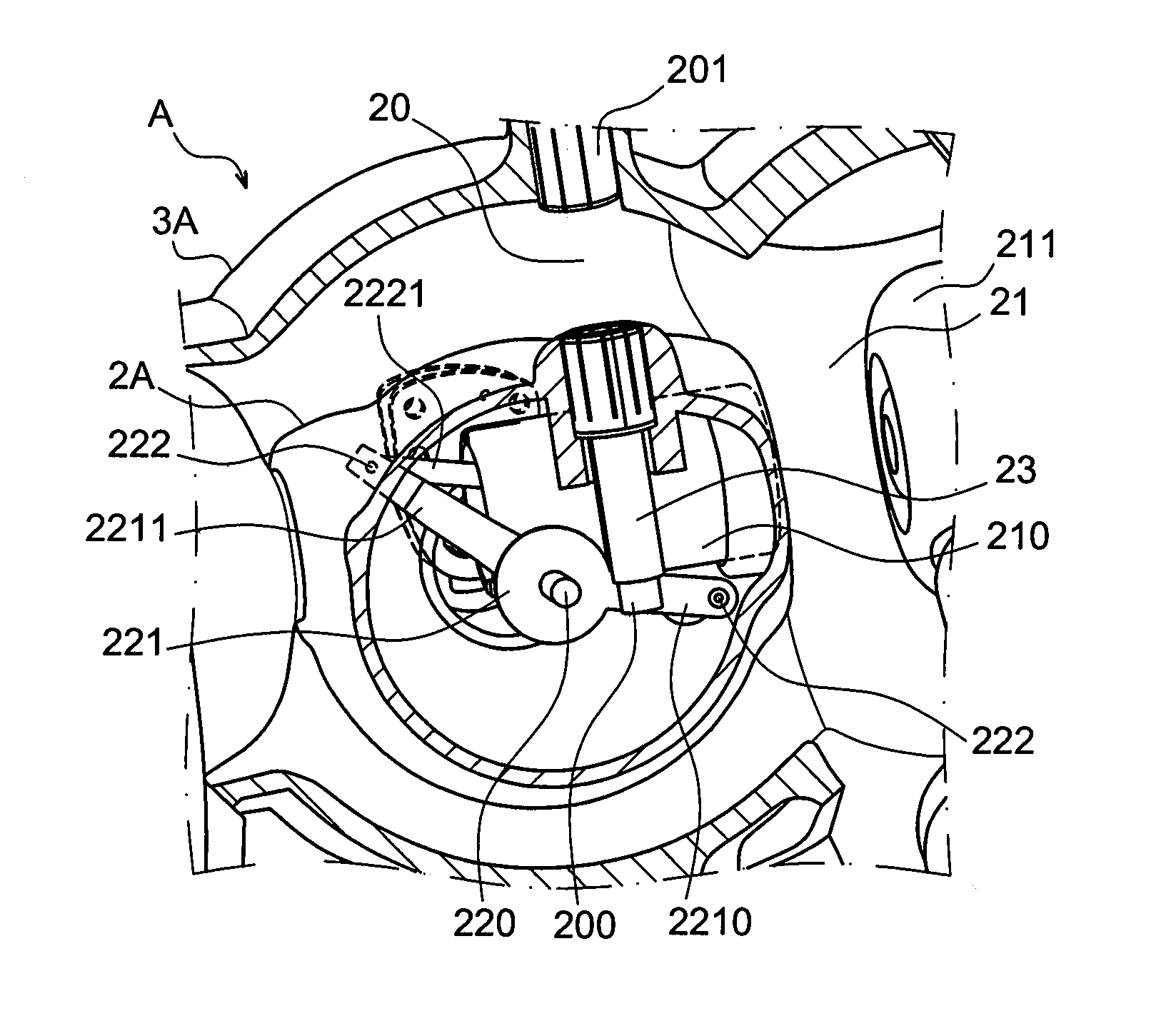
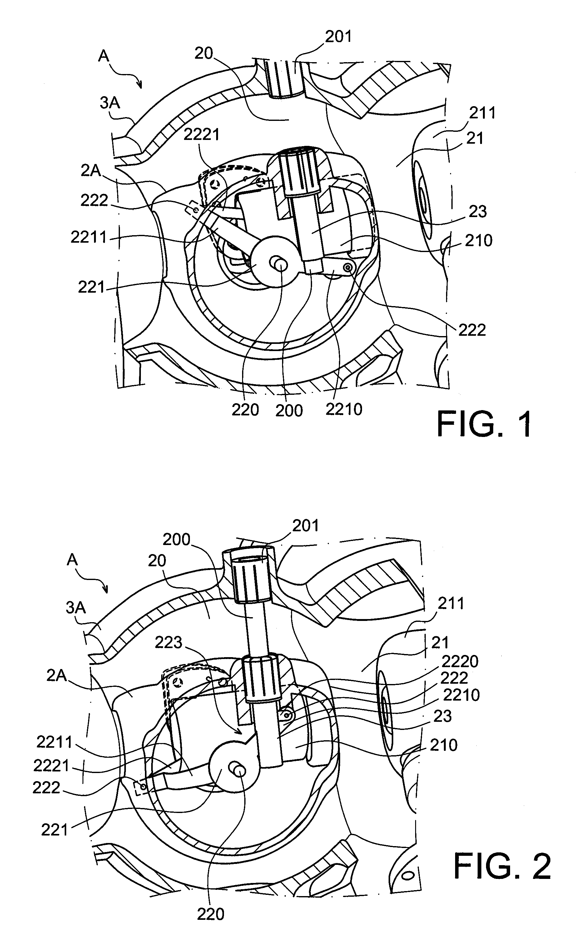
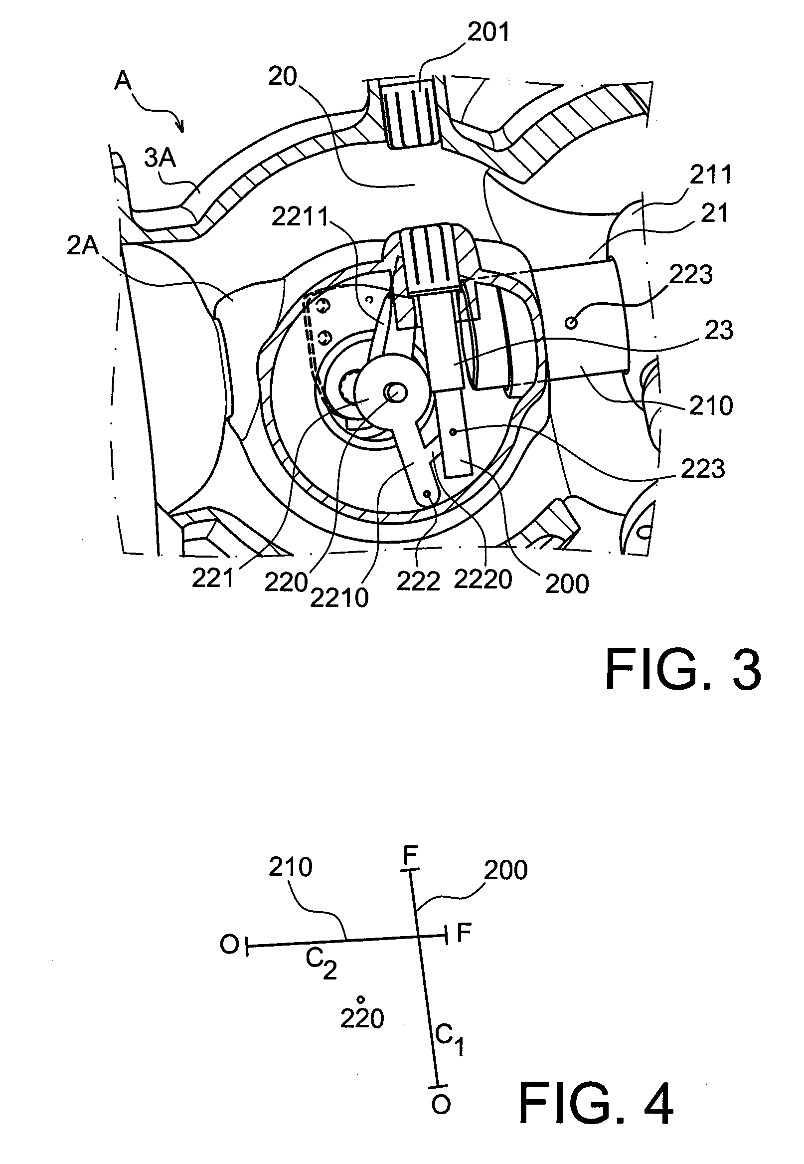
[0055]The drawings described below show a switch apparatus A, constructed in accordance with this invention, that effects switching of one pole. It goes without saying that the arrangement described below for a switch apparatus can be repeated for each pole of a multi-polar combination.

[0056]FIG. 1 shows part of a three-phase switch (switchgear unit) 1, having three identical switch casings. Only one switch casing, 2A, is shown. A switch apparatus constructed in accordance with the invention is contained inside this switch casing. Each of the three identical phases is arranged in its own metal casing. The only one of these casings shown here is the casing 3A containing the corresponding casing 2A.

[0057]In the embodiment shown in FIGS. 1 to 3, the grounding disconnector 20 and the busbar disconnector 21 of the phase 2A are disposed substantially in one plane, being superimposed, or in other words offset along the axis of rotation X. The disconnectors 20 and 21 define an angle of 90° ...


PUM


Abstract

A switch apparatus comprising two interrupters, such as a busbar disconnector and a grounding disconnector. Common actuator means are provided for the movable contacts of the interrupters, for permitting one of the interrupters to be opened while holding the other interrupter closed, and vice versa, which enables the strokes performed by the movable contacts to be crossed.

Description

CROSS REFERENCE TO RELATED APPLICATIONS or PRIORITY CLAIM[0001]This application claims priority of French Patent Application No. 08 56952, filed Oct. 14, 2008.TECHNICAL FIELD[0002]This invention relates in general terms to the field of high or medium voltage switch apparatus having two interrupters, such as a busbar disconnector and a grounding disconnector.[0003]In particular, the invention relates to those kinds of switch apparatus in which one of the interrupters is a busbar disconnector and the other interrupter is a grounding disconnector.[0004]More specifically, the invention relates to that type of switch apparatus in which each interrupter, for example a disconnector, has a pair of contacts that consist of a stationary contact and a contact that is movable in straight line movement so as to separate the contacts from each other in a switching operation.[0005]The main application is to medium or high voltages in which the busbar disconnector and grounding disconnector are dis...

Claims


Application Information

Patent Timeline
Patent Type & Authority Applications(United States)
IPC IPC(8): H01H3/04
CPCH01H31/003H01H3/46H01H33/02
Inventor GELLOZ, BERNARDRECH, CHRISTOPHE
Owner ALSTOM TECH LTD
Why Eureka
Try Eureka