High accuracy fuel metering system for turbine engines

a turbine engine and high-accuracy technology, applied in the direction of engines, machines/engines, mechanical equipment, etc., can solve the problems of complex and expensive control system of typical gas turbine engines, system does not have a piston pump with a very high volumetric efficiency, and device is too small to be used with turbine engines

Active Publication Date: 2006-02-14
HONEYWELL INT INC
View PDF14 Cites 23 Cited by
  • Summary
  • Abstract
  • Description
  • Claims
  • Application Information

AI Technical Summary

Benefits of technology

[0021]A further aspect of the invention is to prevent extremely high pressure situations by providing a pump relief valve should the metered flow discharge port be inadvertently blocked.
[0025]A still further aspect of the invention is to provide a piston pump that has a very high volumetric efficiency and very low leakage so that the amount of fuel pumped per revolution of the piston pump is a known constant.
[0026]According to an aspect of the invention, the piston pump pumps the same volume of fuel independent of output pressure. The amount of leakage in a piston pump is very low.
[0028]Additionally, in the present invention, an aspect of the system is that it seeks precision of the fuel control so that an accuracy of better than + / −3% over a 40:1 fuel flow range can be achieved.

Problems solved by technology

The typical gas turbine engine control system is complex and expensive if high fuel metering accuracy is required.
This device is too small to be used with turbine engines and there is no piston pump driven by a speed controlled electric motor to meter fuel.
However, the pump is not a piston pump and it is not driven by a speed controlled electric motor wherein the piston pump meters fuel to the turbine engine.
Still, this system does not have a piston pump with a very high volumetric efficiency and very low leakage so that an amount of fuel pumped per revolution of the piston pump can be a known constant.
The use of two motors is inefficient in both cost and power.

Method used


Image

  • High accuracy fuel metering system for turbine engines
  • High accuracy fuel metering system for turbine engines

Examples


Embodiment Construction

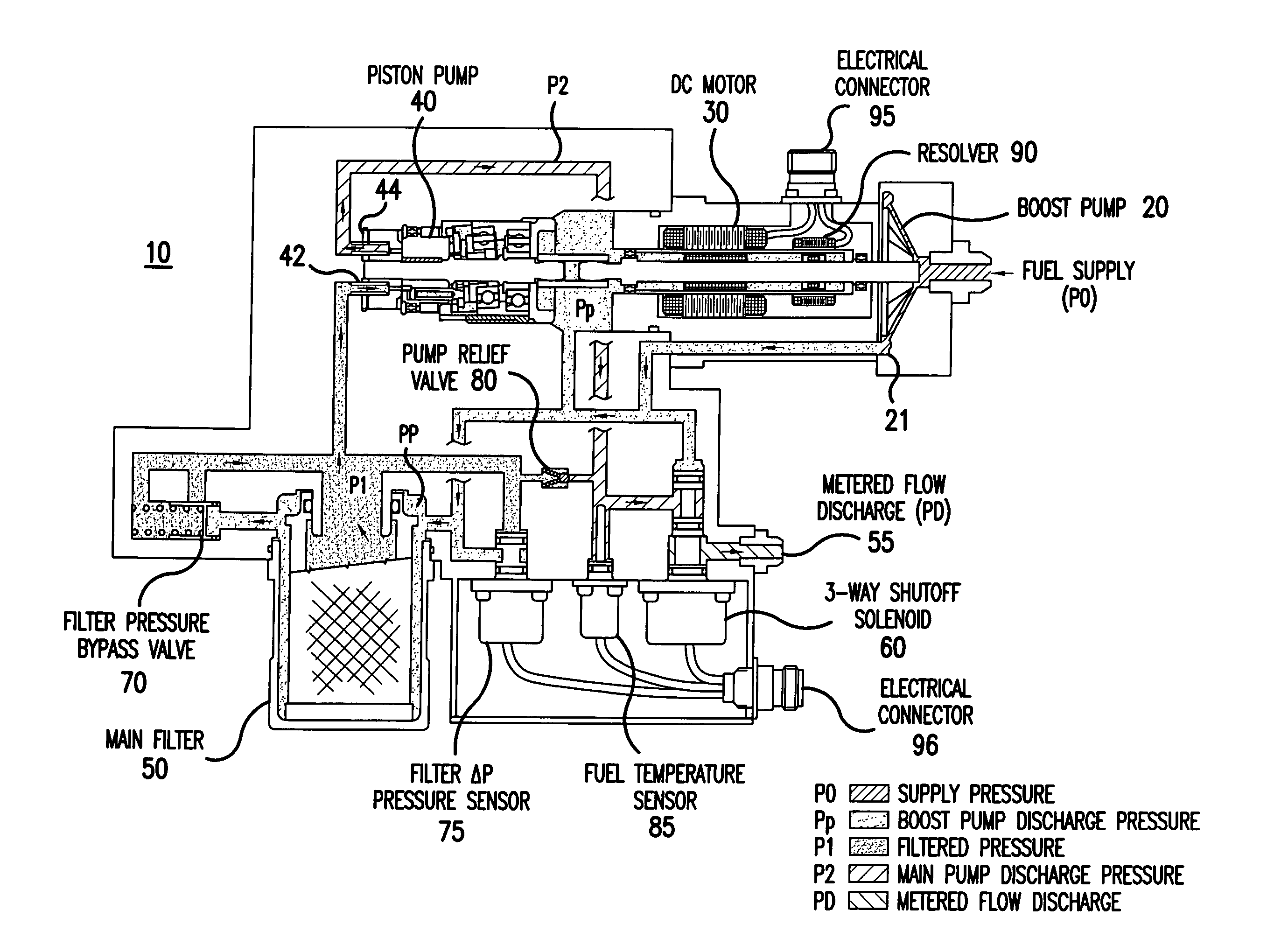
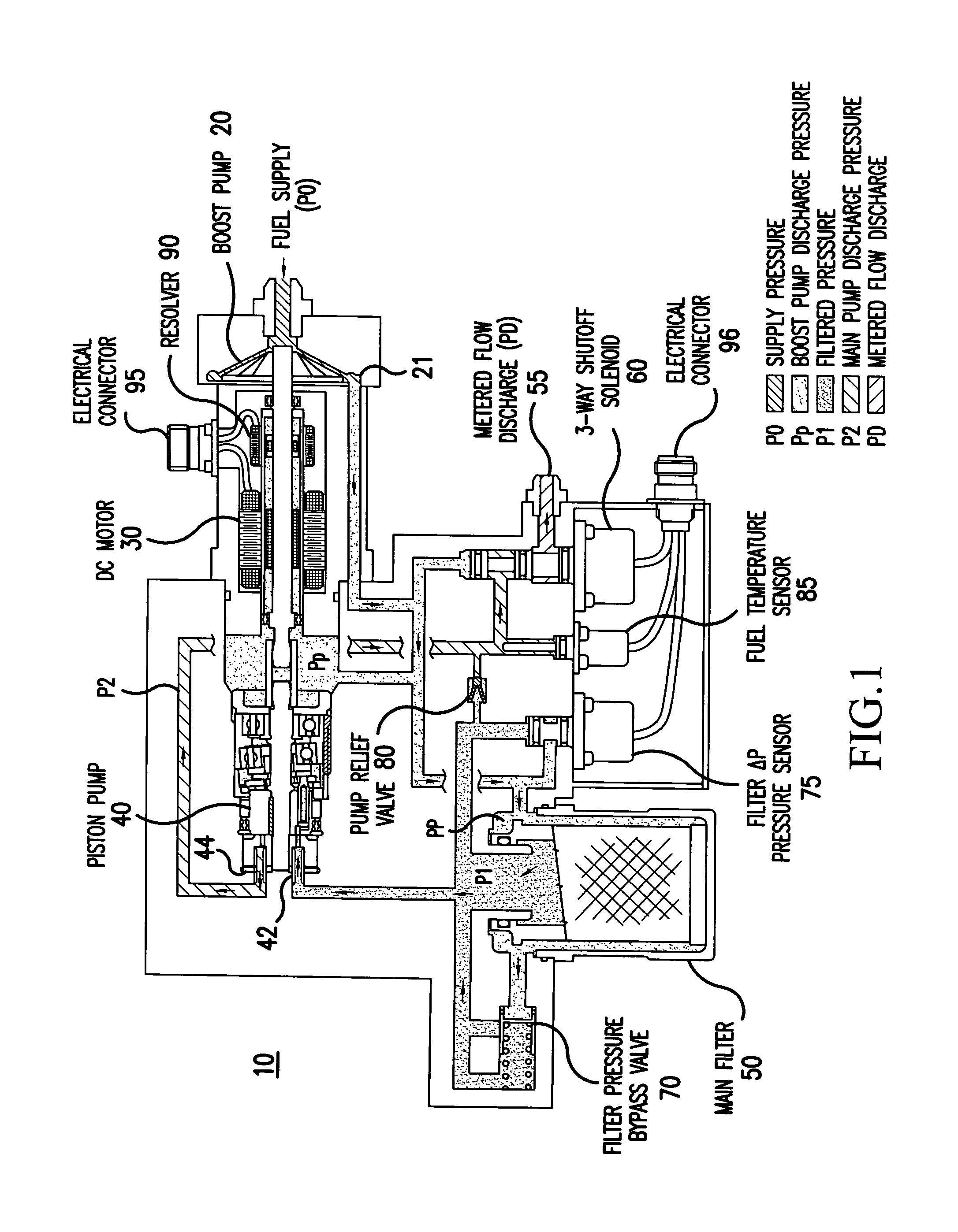
[0031]With reference to the figure, fuel from a fuel tank (not shown) enters a fuel control system of the present invention, generally indicated by the reference numeral 10, at a fuel inlet with a fuel supply pressure (P0). After entering the inlet, the fuel supply pressure (P0) is increased by a centrifugal boost pump 20. The centrifugal pump is utilized in this embodiment. A variable speed brushless DC motor 30 drives the boost pump 20. Also, the motor 30 drives a piston pump 40.

[0032]The fuel exits the boost pump 20 through boost pump outlet 21. This fuel is at a boost pump discharge pressure (PP) and is sent to the outside of a main fuel filter 50. This boost pump discharge pressure (PP) also includes leakage flow from the piston pump 40 and boost pump 20 and is used to keep the motor 30 cool.

[0033]After passing through the main fuel filter 50, the fuel is at a filtered pressure (P1) and enters inlet 42 of the piston pump 40. The piston pump 40 driven by the electric motor 30 bo...


PUM


Abstract

A fuel control system (10) in a turbine engine includes a centrifugal boost pump (20) that receives fuel from a fuel tank and increases the pressure of the fuel. A piston pump (40) boosts the fuel pressure to levels required by the turbine engine and meters an amount of fuel delivered to the turbine engine. A speed controlled electric motor (30) drives the piston pump (40). The electric motor (30) is driven by an electronic speed control wherein by controlling motor speed, fuel flow to the turbine engine is controlled, and fuel flow is directly proportional to the speed of the motor (30). Accordingly, the system (10) seeks precision of fuel control that can be achieved with an accuracy of better than + / −3% over a 30:1 fuel flow range.

Description

CROSS REFERENCE TO RELATED APPLICATION[0001]This Nonprovisional application claims priority under 35 U.S.C. § 119(e) on U.S. Provisional Application No. 60 / 506,744 filed on Sep. 30, 2003, the entire contents of which are hereby incorporated by reference.[0002]This invention was made with Government support under Contract No. N00019-02-C-3002 awarded by the United States Navy. The Government has certain rights in this invention.BACKGROUND OF THE INVENTION[0003]1. Field of the Invention[0004]The present invention relates to a fuel metering system for turbine engines.[0005]More specifically, the present invention relates to a highly accurate fuel metering system with a low leakage piston pump wherein fuel metering is accomplished by using a variable speed electric motor to drive the piston pump. Fuel flow is directly proportional to motor speed. With a brushless DC motor driving the piston pump speed can be accurately controlled.[0006]2. Description of the Background Art[0007]Many syst...

Claims


Application Information

Patent Timeline
Patent Type & Authority Patents(United States)
IPC IPC(8): F02C7/236F02C9/26F02C9/30
CPCF02C9/30
Inventor LORENZ, WILLIAM
Owner HONEYWELL INT INC
Why Eureka
Try Eureka