Electrically controlled fluid system with ability to operate at low energy conditions

a fluid system and low energy condition technology, applied in electrical control, machines/engines, non-mechanical valves, etc., can solve the problem of limited pressure differential across the valv

Active Publication Date: 2006-02-14
CATERPILLAR INC +1
View PDF17 Cites 10 Cited by
  • Summary
  • Abstract
  • Description
  • Claims
  • Application Information

AI Technical Summary

Problems solved by technology

If the electrical energy available to the electrical actuator is less than a predetermined electrical energy, a pressure differential across the valve is limited.

Method used


Image

  • Electrically controlled fluid system with ability to operate at low energy conditions
  • Electrically controlled fluid system with ability to operate at low energy conditions
  • Electrically controlled fluid system with ability to operate at low energy conditions

Examples


Embodiment Construction

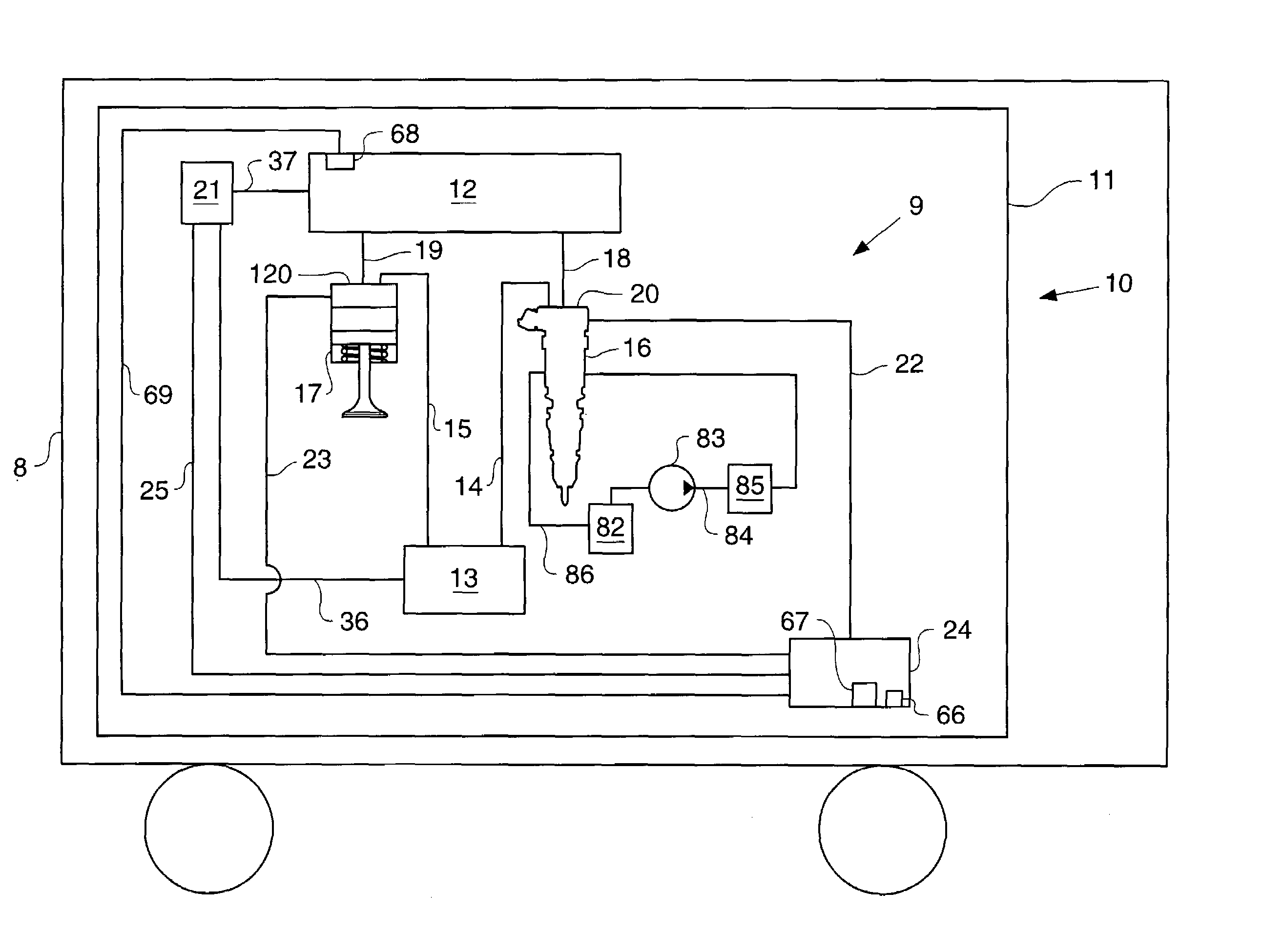
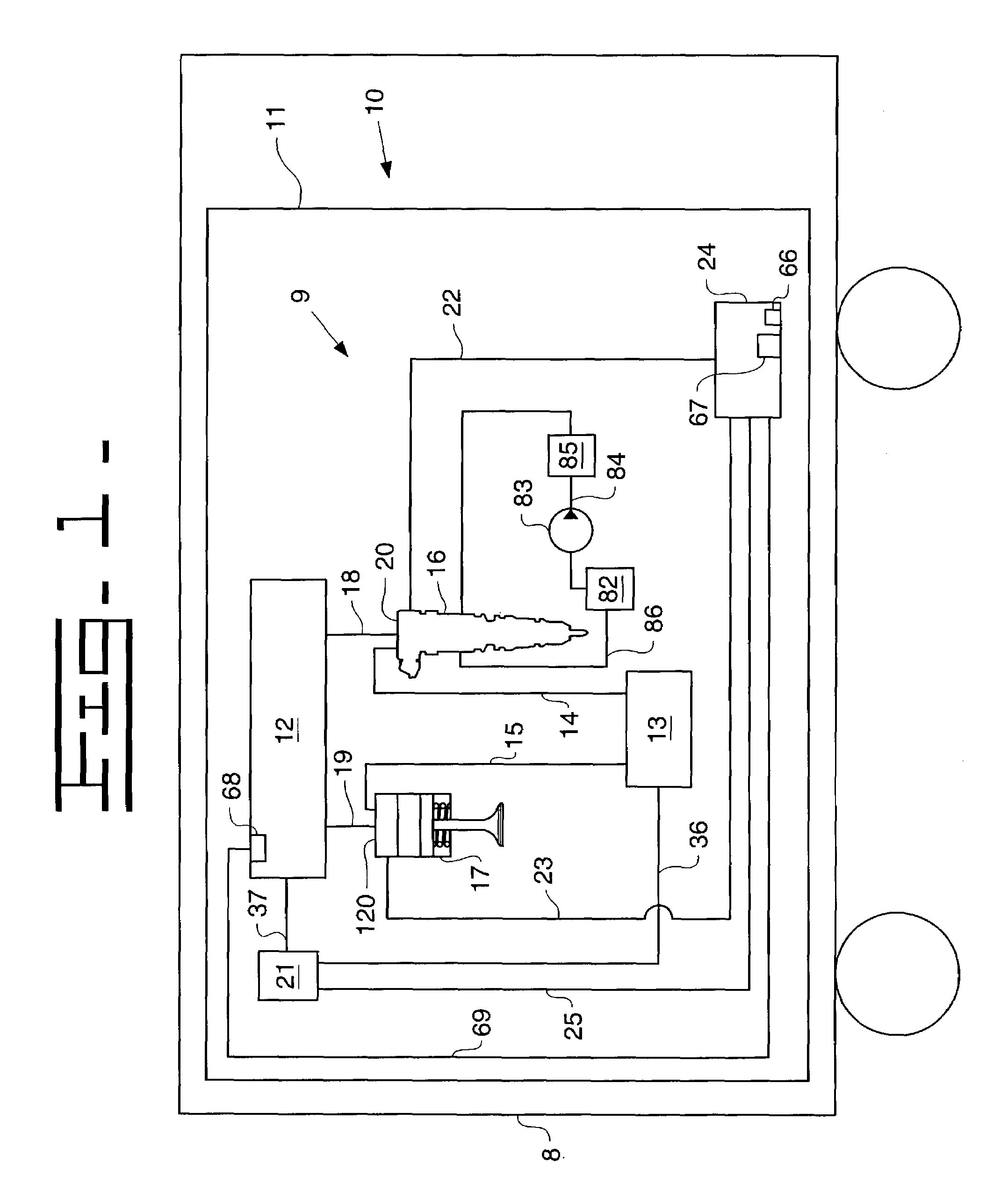
[0016]Referring to FIG. 1, there is shown an electrically-controlled fluid system according to the present invention. In the example embodiment, the fluid system is a hydraulic system 9 within an engine 10 attached to a vehicle 8. However, it should be appreciated that the present invention could be utilized in any electronically-controlled fluid system, regardless of whether the fluid system is a hydraulic system or part of an engine. The engine 10 includes an engine housing 11 to which a low pressure actuation fluid reservoir 13 is attached. While low pressure actuation fluid reservoir 13 is preferably an oil pan that has engine lubricating oil, it should be appreciated that other fluid sources having an amount of available fluid, such as coolant, transmission fluid or fuel, could instead be used. A pump 21 pumps actuation fluid from the low pressure reservoir 13 via a low pressure supply line 36 and delivers the same via a high pressure supply line 37 to a source of pressurized f...


PUM


Abstract

Electrically controlled fuel injection systems should be able to operate at low voltage. In order to operate an electrically controlled fuel injection system at low voltage, the voltage available to an electrical actuator is monitored. The electrical actuator is coupled to a valve positioned within a passageway in which high pressure actuation fluid flows to and from an hydraulically actuated device, such as a fuel injector and / or an engine brake. If the voltage available to the electrical actuator falls below a predetermined voltage, the pressure differential across the valve is reduced. Although the principal application of the present invention is in the fuel injection system, the present invention has application in any electrically controlled fluid system at low voltage.

Description

TECHNICAL FIELD[0001]The present invention relates generally to electrically controlled fluid systems, and more particularly to a method for operating electrically controlled valves within the system during periods of low energy availability.BACKGROUND[0002]In several diesel engines today, hydraulically-actuated devices, such as hydraulically-actuated fuel injectors and engine brakes, are controlled by electrically-actuated fluid control valves. Depending on the positioning of a valve member, the fluid control valve either connects the hydraulic device to a source of high pressure actuation fluid causing the device to activate, or connects the hydraulic device to a low pressure actuation reservoir causing the device to deactivate, reset itself, or remain inactive. The movement of the valve member is controlled by an electrical actuator, such as a solenoid or piezo actuator. For instance, hydraulically actuated fuel injectors such as that shown in U.S. Pat. No. 5,738,075 issued to Ch...

Claims


Application Information

Patent Timeline
Patent Type & Authority Patents(United States)
IPC IPC(8): F02D13/04F01L9/00F02M51/00F02D41/38F02M57/02F02M59/46F02M63/02
CPCF02M63/0047F02M57/025F02M59/366F02M63/0015F02M51/061F02D41/3836F02D2200/503F02D2250/31
Inventor STOCKNER, ALAN R.SCHULZ, RENEOHLIGSCHLAEGER, OLAFSHINOGLE, RONALD D.KIRSCH, BERNHARDCOTTON, III, CLIFFORD E.
Owner CATERPILLAR INC
Why Eureka
Try Eureka