Connector

a connector and connector technology, applied in the direction of fixed connections, coupling device connections, instruments, etc., can solve the problems of difficult assembly process of connectors and printed circuit boards, electrical or mechanical connection relationships between printed circuit boards, and insufficient mechanical coupling force of saddle mount connectors, etc., to achieve easy coupling of connectors to printed circuit boards, the effect of mechanically coupling reliable results

Inactive Publication Date: 2006-02-14
JST MFG CO LTD
View PDF10 Cites 15 Cited by
  • Summary
  • Abstract
  • Description
  • Claims
  • Application Information

AI Technical Summary

Benefits of technology

[0016]The present invention has been made to solve the above-mentioned situations, and an object of the present invention is to provide a straddle mount type connector in which an assembly of a connector and a printed circuit board is easily performed and which has a holding structure capable of reliably coupling the connector to the printed circuit board.
[0030]As described above, in the connector according to the present invention, the edge of the printed circuit board is gripped by the pair of first protrusions. Further, both two side portions of the rectangular slot support the plurality of the second protrusions on the respective supporting surfaces. Therefore, the connector and the printed circuit board can be more reliably mechanically coupled to each other. The printed circuit board coupled to the connector can stand the external force applied to the plane of the connector.
[0033]That is, a step exists between the first extension part and the second extension part, and the printed circuit board moves along the step surface, such that it is possible to insert the printed circuit board without aiming the board in the conventional manner. Thus, the assembly can be easily performed.
[0043]According to the present invention, in a straddle mount type connector, the edge of the printed circuit board is gripped by the pair of first protrusions, and both the wings of the rectangular slot are held by the plurality of second protrusions, such that the connector and the printed circuit board can be reliably mechanically coupled to each other.
[0044]Further, there exists a step between the first extension part and the second extension part of each of the pair of first protrusions, and the printed circuit board moves in parallel along the step surface, such that it is possible to insert a part of the printed circuit board without aiming in a conventional manner. Thus, it is possible to easily couple the connector to the printed circuit board.

Problems solved by technology

The straddle mount type connector has no sufficient mechanical coupling force because only the weak lead parts are soldered to the edge connector.
On the other hand, when the connector housing is reliably fixed to the printed circuit board using a fastener such as a screw, a trouble may occur in the electrical or mechanical connection relationship between the printed circuit board and the connector, or the assembly process of the connector and the printed circuit board may be difficult.
In the above-described straddle mount type connector for a memory card, even though a gripper arm assembly having the receiving space formed by the upper gripper arm and the lower gripper arm is arranged at the one side surface of the memory card connector, it is considerably difficult to insert and assemble the printed circuit board so as not to collide with the opposing contact lead parts.

Method used


Image

  • Connector
  • Connector
  • Connector

Examples


Embodiment Construction

[0052]The preferred embodiment of the present invention will be described below in reference to the drawings. However, the present invention is not limited to the embodiment, and various modifications and changes in design can be made without departing from the scope of the present invention.

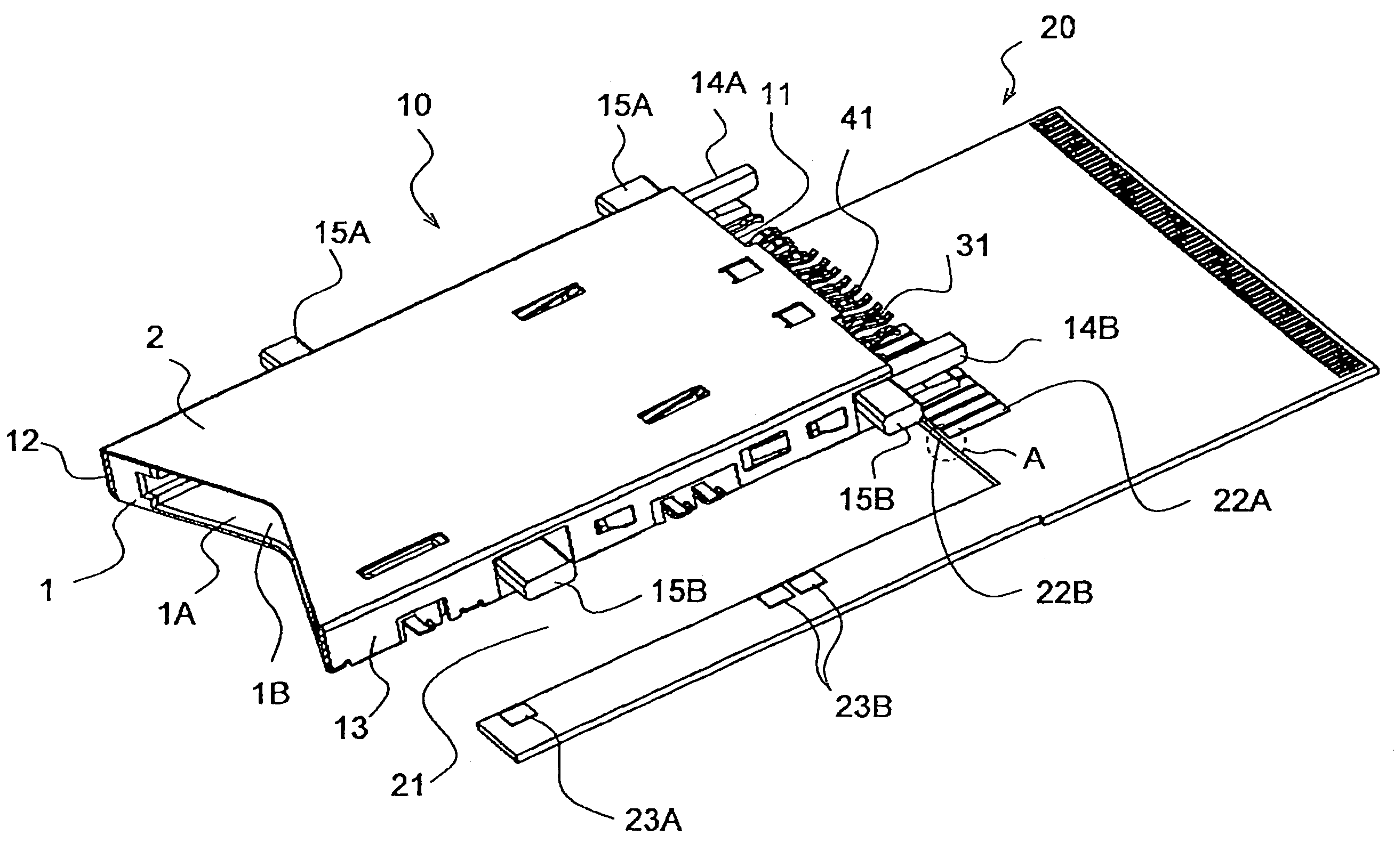
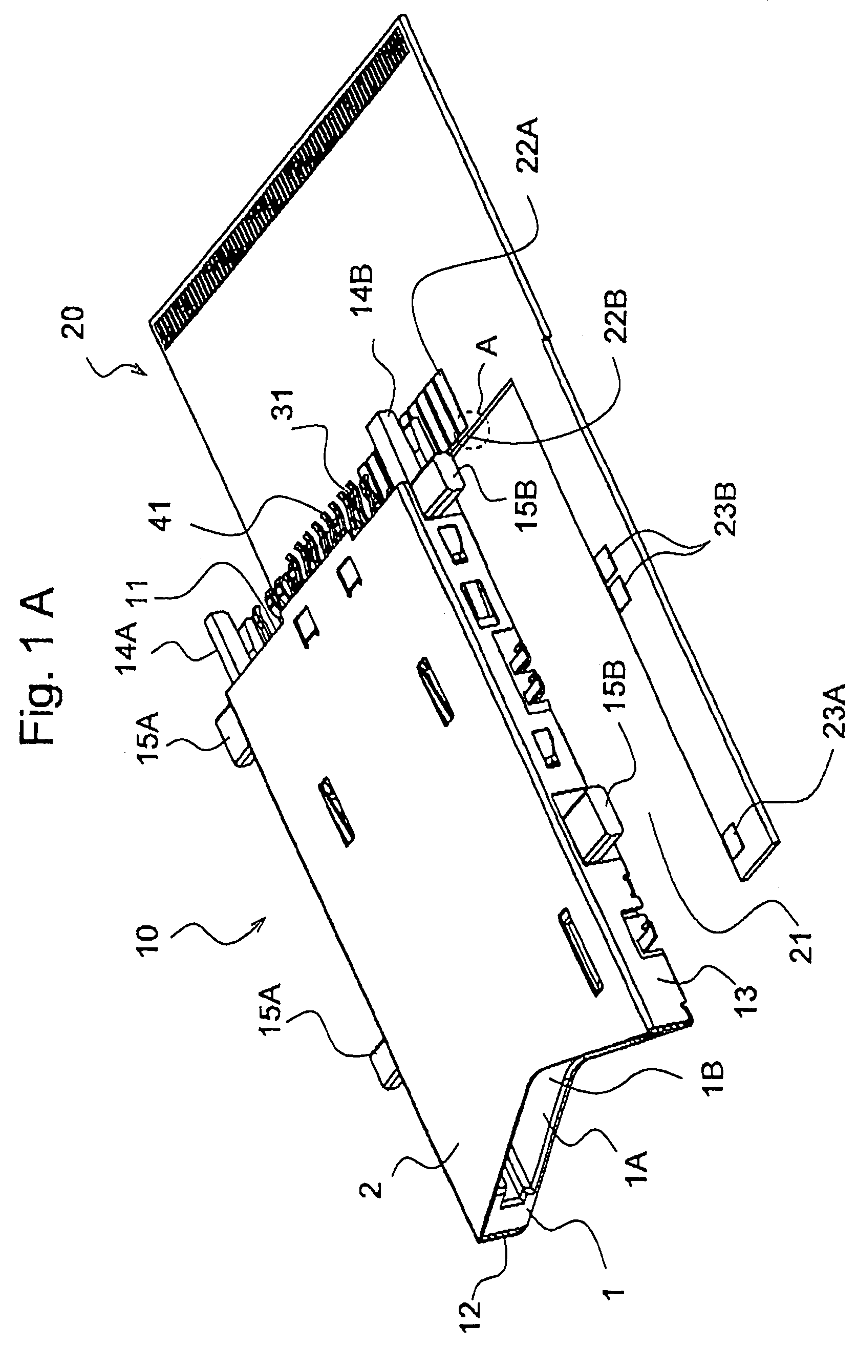
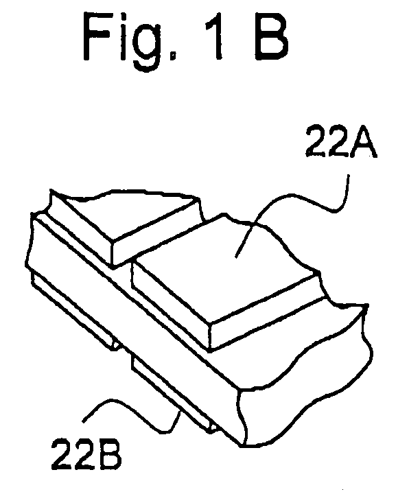
[0053]FIGS. 1A and 1B are perspective views showing the external appearance of a straddle mount type connector for a memory card (hereinafter, referred to as a connector) according to an embodiment of the present invention. In a connector 10 of FIG. 1A, reference numeral 1 designates a housing, reference numeral 2 designates a cover, and reference numeral 20 designates a printed circuit board on which the connector 10 is mounted.

[0054]In the embodiment of FIG. 1A, the housing 1 is made of an insulating synthetic resin with a rectangular shape. The cover 2 is composed of a metal plate, and both wings (side portions) thereof are bent in an ‘L’ shape. Further, the cover 2 is attached to the housing...


PUM


Abstract

The present invention provides a connector capable of being easily and reliably coupled to a printed circuit board. A connector (10) comprises two sets of a plurality of lead parts (31) and a plurality of lead parts (41) extending from one side surface (11) of a housing (1) to be opposite to each other. A printed circuit board (20) includes slot (21) abutting on the side surfaces (11) to (13) of the housing (1), and edge connectors (22A) and (22B) are formed on both surfaces of an edge abutting on the one side surface (11). The edge connectors (22A) and (22B) are inserted between the lead parts (31) and (41), and the lead parts (31) and (41) are soldered to the edge connectors (22A) and (22B), respectively. In a pair of first protrusions (14A) and (15B), a recess (140) for gripping the printed circuit board (20) is formed, and the recess (140) is aligned in the same row as the opposing gap between the lead parts (31) and (41), The second protrusions (15A) and (15B) each have a supporting surface abutting on one surface of the printed circuit board (20), and respectively protrude from the side surfaces (12) and (13) arranged opposite to each other.

Description

CROSS-REFERENCE TO RELATED APPLICATIONS[0001]This application is based upon and claims the benefits of priorities from Japanese Patent Application No. 2003-402294 filed on Dec. 1, 2003, the entire contents of which are incorporated herein by reference.[0002]This application is related to co-pending U.S. patent applications Ser. Nos. 11 / 000,031 and 11 / 000,078. The co-pending applications are expressly incorporated herein by reference.FIELD OF THE INVENTION[0003]The present invention relates to an electrically connectable connector. More specifically, the present invention relates to a straddle mount type connector in which a printed circuit board is interposed between contact lead parts extending to a rear portion of the connector such that the contact lead parts are electrically connected to the printed circuit board by soldering. The straddle mount type connector is a kind of surface mounting type connectors.RELATED ART[0004]With the development of a surface mount technology (SMT),...

Claims


Application Information

Patent Timeline
Patent Type & Authority Patents(United States)
IPC IPC(8): H01R24/00G06K17/00H01R12/57H01R12/70
CPCH01R12/707H01R12/57H01R12/71G06K17/00
Inventor KATO, MASATOFUKUZAKI, HIROSHIFUKAMI, TSUYOSHIKASAMARU, YOICHITAKAI, MASAHARU
Owner JST MFG CO LTD
Why Eureka
Try Eureka