Optical apparatus

a technology of optical instruments and polarizing light, which is applied in the direction of optical radiation measurement, instruments, polarising elements, etc., can solve the problems of difficult to create linearly polarized light from non-polarized light sources, difficult to choose between s-polarized light and p-polarized light, and difficult to measure reflectance with accuracy. , to achieve the effect of easy change of polarization planes, high degree of polarization, and easy high-precision measuremen

Inactive Publication Date: 2006-02-14
CANON KK
View PDF17 Cites 57 Cited by
  • Summary
  • Abstract
  • Description
  • Claims
  • Application Information

AI Technical Summary

Benefits of technology

The technical effect of this patent is to create an optical device that can quickly switch between different levels of polarization without losing much energy or accuracy when measuring things like electric fields. This makes it easier to use non-linearly polarized light sources which are commonly available today.

Problems solved by technology

The technical problem addressed in this patent text is the difficulty of accurately measuring the reflectance of optical materials at various angles and positions due to the lack of easily available tools capable of providing a stable and controlled level of polarization for both p-polarized and s-polarized light sources. Conventional methods require either costly and complex equipment or time-consuming procedures to achieve optimal results. There is also a challenge in identifying the orientation of the reflected objects without turning them repeatedly, especially if they are multi-layer samples.

Method used


Image

  • Optical apparatus
  • Optical apparatus
  • Optical apparatus

Examples


Embodiment Construction

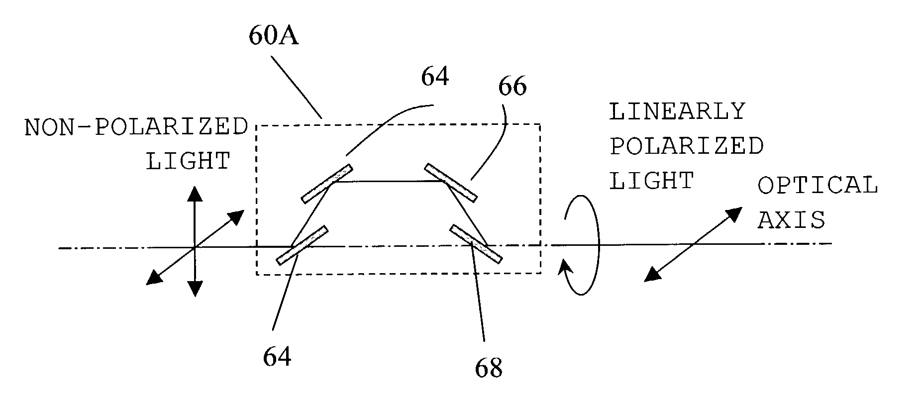
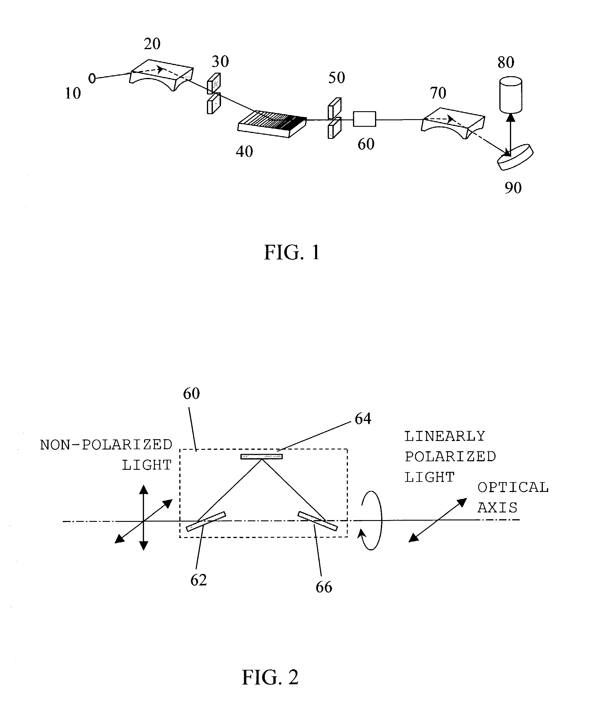
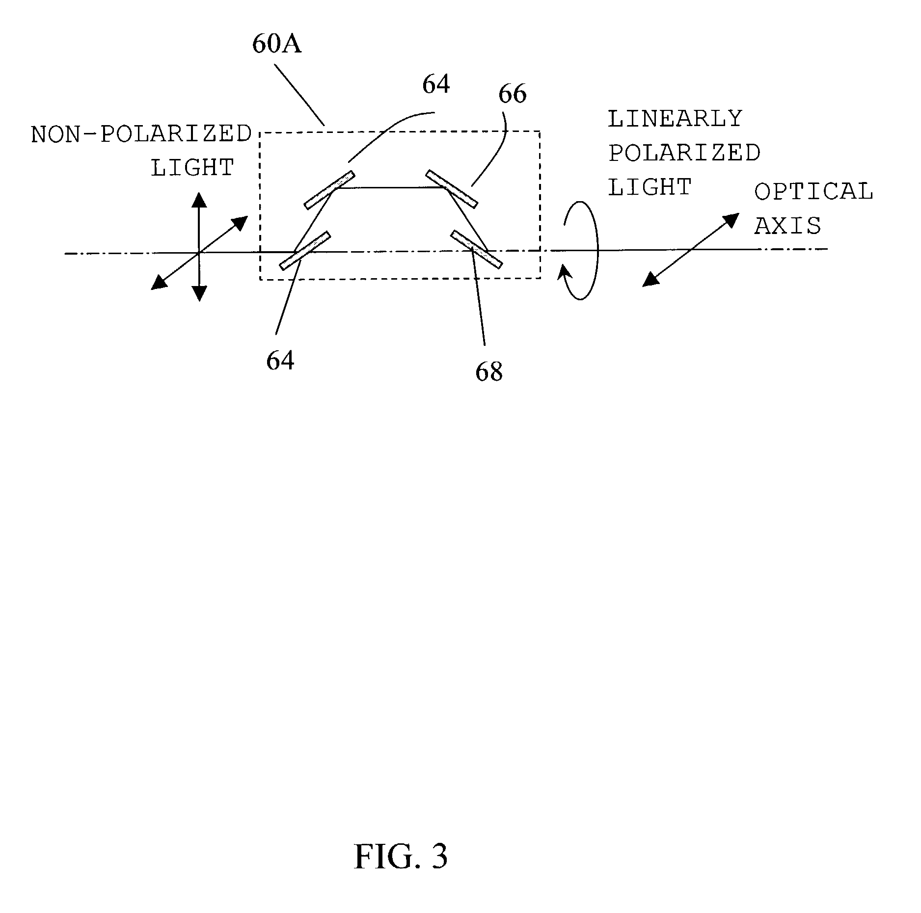
[0039]Referring to the accompanying drawings, a description will now be given below of a reflectance measuring apparatus 1, and a photoelectron spectrometer 2, as examples of the optical apparatus of the present invention. Of course, the present invention is not limited to these embodiments, and within the sphere in which the object of this invention is achieved, each component may be alternatively substituted. Here, FIG. 1 is a schematic view of the reflectance measuring apparatus 1. As shown in FIG. 1, the reflectance measuring apparatus 1 includes a light source 10, a prefocusing mirror 20, a slit 30, a diffraction grating 40, a slit 50, a polarizer 60, a postfocusing mirror 70 and a detector 80, thus measuring reflectance of a measured object 90.

[0040]The light source 10 is a plasma light source (for example, LLP light source) in the EUV X-ray region, which emits a divergent pencil of rays that are isotropically non-polarized and have a continuous wavelength. The prefocusing mir...


PUM


Abstract

An optical apparatus that measures a polarization dependent characteristic of a measured object includes a light source for emitting non-linearly polarized light in an extreme ultraviolet region or an X-ray region, and a rotary polarizer for reflecting the light emitted from the light source, the polarizer including a set of mirrors repeating three or more reflections and being arranged such that an optical axis of incident light and that of outgoing light are aligned with the same straight line.

Description


Claims


Application Information

Patent Timeline
Owner CANON KK
Why Eureka
Try Eureka