Flying head slider capable of avoiding collision when loaded

Inactive Publication Date: 2006-02-14
TOSHIBA STORAGE DEVICE CORP
View PDF27 Cites 2 Cited by
  • Summary
  • Abstract
  • Description
  • Claims
  • Application Information

AI Technical Summary

Benefits of technology

[0013]The front surface allows generation of a relatively larger lift on the flying head slider at the moment when the flying head slider falls and starts receiving the airflow in the aforementioned manner. Consequently, the amount of f

Problems solved by technology

Without the support of the ramp, the head slider cannot keep distanced from the surface of the magnetic recording disk when the magnetic recording disk stands still.
In this case, the head slider cannot keep distanced from the surface of the magnetic recording disk without a lift resulting from an airflow generated along the surface of the rotating magnetic recording disk.
If the head slider takes an inclined attitude different from a predetermined normal or horizontal attitude, the head slider cannot receive a lift enough to fly above the surface of the magnetic recording disk.
In particular, the head slider including a front rail exten

Method used


Image

  • Flying head slider capable of avoiding collision when loaded
  • Flying head slider capable of avoiding collision when loaded
  • Flying head slider capable of avoiding collision when loaded

Examples


Embodiment Construction

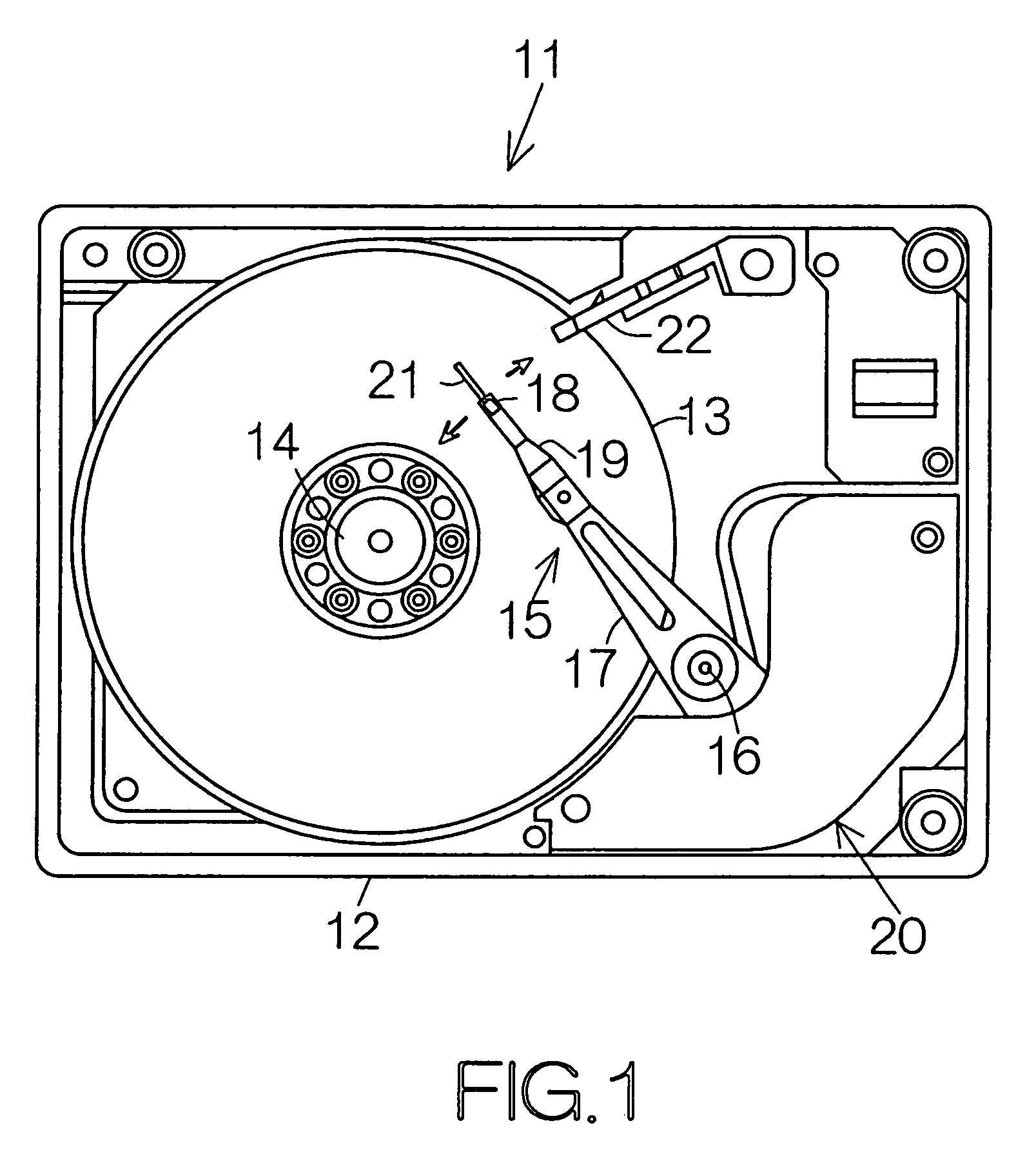
[0033]FIG. 1 schematically illustrates the inner structure of a hard disk drive (HDD) as an example of a recording medium drive. The HDD 11 includes a box-shaped primary enclosure 12 defining an inner space of a parallelepiped, for example. At least one magnetic recording disk 13 is accommodated in the inner space of the primary enclosure 12. The magnetic recording disk 13 is mounted on a driving shaft of a spindle motor 14. The spindle motor 14 is designed to drive the magnetic recording disk 13 for rotation at a higher rate such as 7,200 rpm or 10,000 rpm, for example. A cover, not shown, is coupled to the primary enclosure 12 so as to seamlessly close the inner space of the primary enclosure 12.

[0034]A carriage 15 is also accommodated in the inner space of the primary enclosure 12. The carriage 15 is designed to oppose its tip end to the surface of the magnetic recording disk 13. The carriage 15 includes a swinging arm 17 designed to swing around a support shaft 16, and a head su...


PUM


Abstract

A flying head slider includes a slider body. The upstream or leading end of a bottom surface on the slider body is defined along a first datum line extending in the lateral direction of the slider body. The first datum line may be set perpendicular to the longitudinal centerline of the slider body. The upstream or leading end of the front air bearing surface is defined along a second datum line intersecting the first datum line at a predetermined inclined angle. As the incidence angle of an airflow colliding against a step defined at the leading end of the front air bearing surface gets decreased, the pitch angle of the slider body also gets decreased in the flying head slider during flight.

Description

[0001]This is a divisional of application Ser. No 09 / 739,944, filed Dec. 18, 2000 now U.S. Pat. No. 6,728,070.BACKGROUND OF THE INVENTION[0002]1. Field of the Invention[0003]The present invention relates to a head slider accommodated in a recording medium drive such as a hard disk drive (HDD), in particular, to a flying head slider comprising a slider body, a generally flat bottom surface defined on the slider body, a front rail standing on the bottom surface at an upstream or windward position, and an air bearing surface defined on the front rail.[0004]2. Description of the Prior Art[0005]A load / unload mechanism employing a ramp is well known in the technical field of a magnetic disk drive such as a hard disk drive (HDD). The ramp is designed to support an elastic head suspension, carrying a head slider at the tip end, when a magnetic recording disk stands still. For example, the ramp serves to cause bending of the head suspension, in response to an outward movement of the head sli...

Claims


Application Information

Patent Timeline
IPC IPC(8): G11B5/60G11B21/21
CPCG11B21/21G11B5/6005G11B5/6082
Inventor KOISHI, RYOSUKE
Owner TOSHIBA STORAGE DEVICE CORP
Why Eureka
Try Eureka