Decoding circuit and method of Viterbi decoder

a decoding circuit and decoding method technology, applied in the field of decoding circuit and decoding method of viterbi decoder, can solve the problems of difficult implementation of high-speed viterbi decoder, large hardware capacity of recording hardware, and long hidden decoding path

Active Publication Date: 2006-02-14
XUESHAN TECH INC
View PDF10 Cites 11 Cited by
  • Summary
  • Abstract
  • Description
  • Claims
  • Application Information

AI Technical Summary

Benefits of technology

[0019]It is therefore an object of the invention to provide a decoding circuit and a decoding method of a Viterbi decoder capable for solving the complicated trellis diagram after the trellis diagram of the Viterbi decoder is subjected to a longitudinal arrangement. In addition, a high decoding speed of the Viterbi decoder can be achieved without requiring a lot of registers for data processing.
[0023]Consequently, the invention provides a decoding circuit and a method for a Viterbi decoder. In this invention, a RLL code is used for effectively solving the problem of generating a complicated trellis diagram after the trellis diagram of the Viterbi decoder is subjected to a longitudinal arrangement. Therefore, the ACS can perform adding and comparing operations in parallel, and the register array can perform other operations at different time. Accordingly, a high decoding speed of the Viterbi decoder can be achieved without requiring a lot of registers for data processing in the ACS and PMU.

Problems solved by technology

Since a feedback loop exists in the ACS unit (the survivor metric of each state has to be re-calculated), it is difficult to implement a high-speed Viterbi decoder.
First, the hidden decoding path is too long.
Second, if the path is too long, the capacity of the hardware for recording will be relatively great (the hardware is called a path memory unit).
However, in the actual implemenattion, it is not possible to perform such a trace-back operation for finding each root.
The disadvantage of the trace-back method is that it is usually implemented using RAMs.
Thus, it is allowable for the application of DVD players but is not allowable in DVD ROMs due to its slow speed.
If registers are used for increasing the speed, a lot of hardware costs should be paid because four blocks are processing the data simultaneously in the trace-back method.
Thus, this method is not suitable for high-priced memories.

Method used


Image

  • Decoding circuit and method of Viterbi decoder
  • Decoding circuit and method of Viterbi decoder
  • Decoding circuit and method of Viterbi decoder

Examples


Embodiment Construction

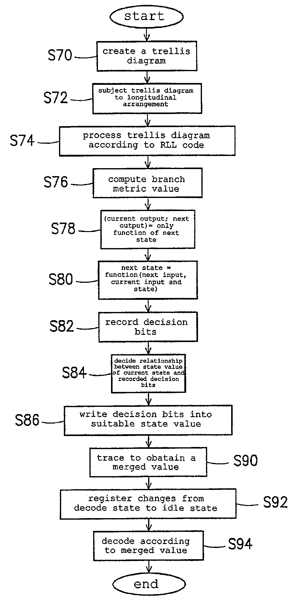
[0048]FIG. 8 is a flow chart showing the method for the Viterbi decoder of the invention. As shown in FIG. 8, a trellis diagram (as shown in FIG. 3) corresponding to the Viterbi decoder is first created in step S70. In order to overcome the bottleneck for the ACS, the trellis diagram of the Viterbi decoder is re-arranged by the re-arranging method including a transverse arrangement and a longitudinal arrangement. Taking the original trellis diagram shown in FIG. 9A and n=2 as an example, FIG. 9B shows a transverse arrangement performed in the original trellis diagram. The so-called transverse arrangement is to merge the trellises. Although the bottleneck of ACS still exists, the time of the bottleneck is lengthened from 1T to nT. Thus, the overall speed limitations of the Viterbi decoder can be eased.

[0049]FIG. 9C is a schematic illustration showing that a longitudinal arrangement is performed in the original trellis diagram. In FIG. 9C, the trellis diagram corresponding to the Vite...


PUM


Abstract

The invention provides a decoding circuit and a decoding method of a Viterbi decoder. The decoding circuit of the Viterbi decoder includes a branch metric unit, an add-compare-select unit and a path memory unit. The path memory unit includes a data string controller, a trace write-in register array, an idling register array and a decoding register array. In this invention, a run length limited code is used for effectively solving the problem of generating a complicated trellis diagram after the trellis diagram of the Viterbi decoder is subjected to a longitudinal arrangement. In addition, the register array can perform other operations at different times. Accordingly, a high decoding speed of the Viterbi decoder can be achieved without requiring a lot of registers for data processing.

Description

BACKGROUND OF THE INVENTION[0001]A. Field of the Invention[0002]The invention relates to a decoding circuit and a decoding method of a Viterbi decoder in a Partial Response Maximum Likelihood (PRML) system of an optical disc. Particularly, the invention relates to a decoding circuit and a decoding method for a Viterbi decoder in a PRML system of an optical disc wherein a run length limited code (RLL Code) is used for effectively simplifying the complicated trellis diagram of the Viterbi decoder after longitudinal arrangement without a lot of registers for data processing.[0003]B. Description of the Related Art[0004]In a PRML system such as a digital versatile disc (DVD) or the like, a trellis diagram can be used for describing the property of a transmission channel with a memory. For example, an input signal EFM (eight to fourteen modulation) of a DVD channel is a binary signal and the channel memory length is 2. Accordingly, the trellis diagram has four states each having two branc...

Claims


Application Information

Patent Timeline
Patent Type & Authority Patents(United States)
IPC IPC(8): H04L27/06H03M13/03H04L5/12H04L1/00
CPCG11B20/10009G11B20/10055G11B20/10287G11B20/10296H04L25/03178H03M5/145H03M13/4107H03M13/4169H03M13/4192H04L1/0054G11B2020/1465G11B2220/2562
Inventor KUO, HUNG-CHENHWU, WEN-YI
Owner XUESHAN TECH INC
Why Eureka
Try Eureka