Antenna mast transport and deployment system

a technology of antenna masts and transport and deployment, applied in the field of antenna systems, can solve the problems of limiting the ability to rapidly deploy multiple patriot missile systems, and therefore multiple amgs, and the wibe system is not adapted to transport and deploy the larger and heavier antenna masts, and achieves the effect of rapid deploymen

Inactive Publication Date: 2006-02-21
RAYTHEON CO
View PDF9 Cites 57 Cited by
  • Summary
  • Abstract
  • Description
  • Claims
  • Application Information

AI Technical Summary

Benefits of technology

[0014]With this particular arrangement, a relatively small and lightweight vehicle cap structure is provided that can be coupled to a relatively small and lightweight vehicle. With the first and second antenna mast deployment mechanisms, the antenna mast can be rapidly deployed.

Problems solved by technology

The requirement to transport the AMG with a large aircraft, which can only carry one AMG, limits the ability to rapidly deploy multiple Patriot Missile Systems, and therefore multiple AMGs, to remote battlefields.
Furthermore, the WIBE system is not adapted to transport and deploy the larger and heavier antenna masts required by the Patriot Missile System.

Method used


Image

  • Antenna mast transport and deployment system
  • Antenna mast transport and deployment system
  • Antenna mast transport and deployment system

Examples


Embodiment Construction

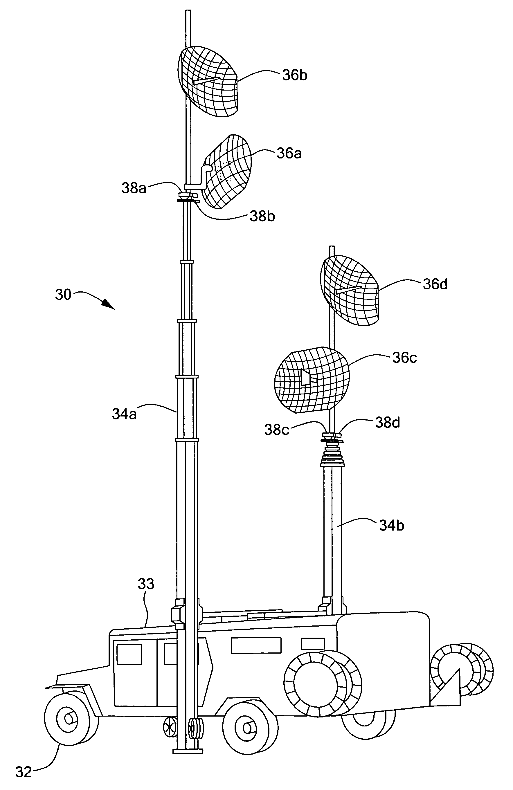
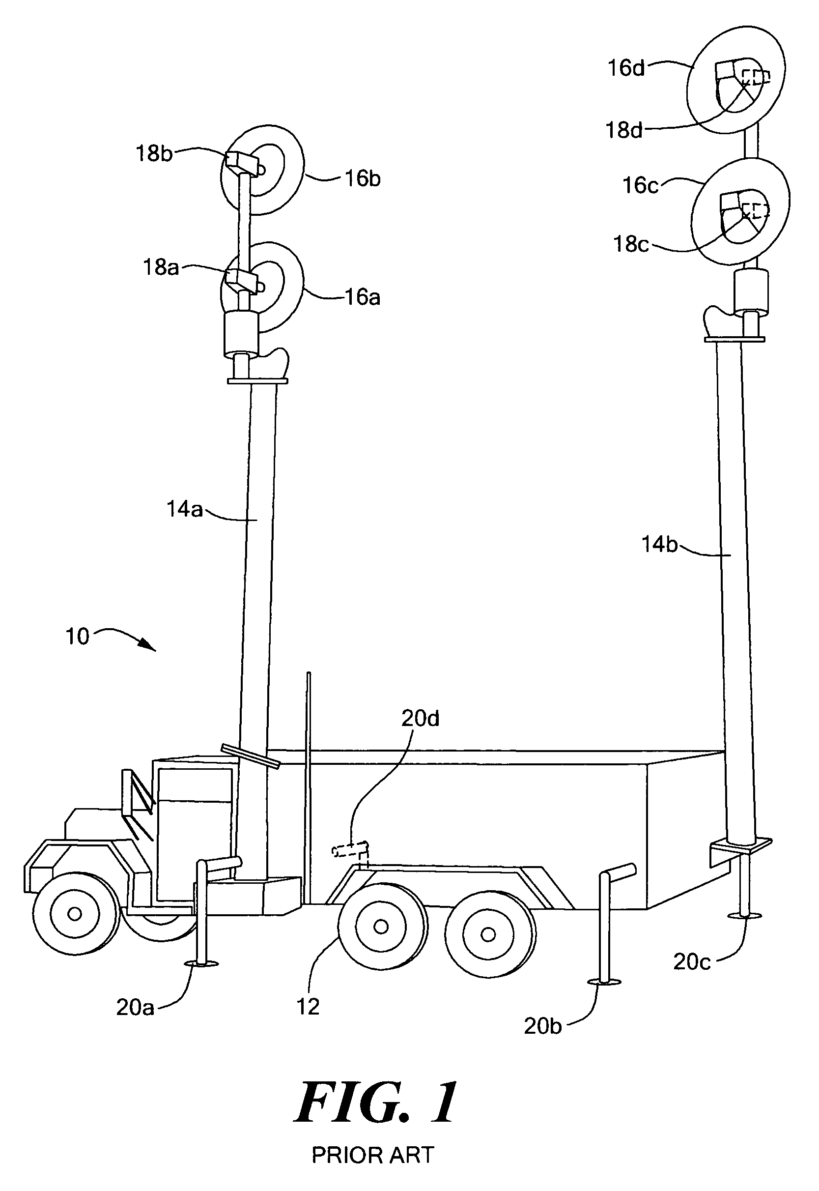
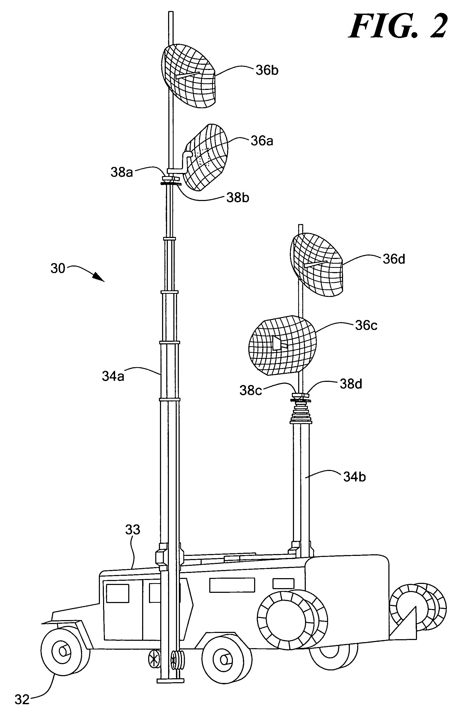
[0027]Referring now to FIG. 1, a prior art antenna mast group (AMG) 10 used as part of the Patriot Missile System includes an M-942 truck 12. The AMG 10 is shown in a deployed configuration.

[0028]Two antenna masts 14a, 14b, each having telescoping tubes, are carried by and deployed from the truck 12. Two antennas 16a–16d are mounted at or near the top of each respective antenna mast 14a, 14b. Each of the antennas 16a–16d is coupled to a respective rotator 18a–18d, which allows independent rotational control of the antennas 16a–16d so that each of the antennas 16a–16d can be independently pointed to a desired direction. The truck 12 includes four outriggers 20a–20d, used to stabilize the truck 12 and antenna masts 14a, 14b.

[0029]Each of the antenna masts 14a, 14b is shown in a vertical position corresponding to a deployed configuration. However, each of the two antenna masts 14a, 14b is in a horizontal position during transport. During deployment, each of the antenna masts 14a, 14b ...


PUM


Abstract

A light antenna mast group (LAMG) provides antenna masts coupled to a vehicle cap structure which is disposed on the top of a light truck, which in one embodiment can be a high mobility multipurpose wheeled vehicle (HMMWV). The vehicle cap structure includes antenna mast deployment mechanisms, hinged rotator assemblies, an antenna storage system, and a plurality of spring loaded guide wire spools, all adapted to make deployment of the antenna masts rapid and simple.

Description

CROSS REFERENCE TO RELATED APPLICATIONS[0001]Not Applicable.STATEMENT REGARDING FEDERALLY SPONSORED RESEARCH[0002]Not Applicable.FIELD OF THE INVENTION[0003]This invention relates generally to antenna systems and more particularly to an antenna system mounted to and deployed from a truck.BACKGROUND OF THE INVENTION[0004]The Patriot Missile System, used by the United States military, includes a variety of subsystems. One such subsystem is the “antenna mast group” (AMG). The AMG includes a truck, e.g., a 5-ton, Model M-942 truck, that transports two antenna masts and associated equipment. The truck also provides a platform from which the two antenna masts are deployed to a vertical orientation. The two antenna masts, when deployed to the vertical orientation, each support two antennas used for communications. Each of the two antennas is coupled to a respective rotator, adapted to independently rotate each of the two antennas to point to a desired direction.[0005]The truck used as part...

Claims


Application Information

Patent Timeline
Patent Type & Authority Patents(United States)
IPC IPC(8): E04H12/00
CPCH01Q1/3216H01Q1/1235
Inventor STEARNS, CRAIG KIMBALROBERGE, RAYMOND ARTHURRICHARDSON, THEODORE ALDEN
Owner RAYTHEON CO
Why Eureka
Try Eureka