Heat exchanger on a turbine cooling circuit

a technology of heat exchanger and cooling circuit, which is applied in the direction of liquid fuel engines, machines/engines, efficient propulsion technologies, etc., can solve the problems of reducing thermodynamic efficiency and heat exchanger becoming clogged with dust blowing out centrifugally, and achieve the effect of reducing the drawbacks

Active Publication Date: 2006-02-21
SN DETUDE & DE CONSTR DE MOTEURS DAVIATION S N E C M A
View PDF10 Cites 65 Cited by
  • Summary
  • Abstract
  • Description
  • Claims
  • Application Information

AI Technical Summary

Benefits of technology

[0010]The object of the invention is to mitigate those drawbacks and to supply a cooler flow of air for cooling the moving blades of the turbine.
[0012]Thus, since the cooling air is bled from the zone at the end of the combustion chamber that surrounds the diffuser, this air contains a smaller quantity of particles, thus limiting clogging of the heat exchanger. In addition, since the blades of the distributor are cooled by a second flow of air bled from the end of the combustion chamber, the cooled air becomes heated to a smaller extent on passing through the distributor, and none of this air is lost therefrom.
[0014]This disposition serves to improve the lifetime of the high pressure compressor, in particular in turbojets for military use which can be subjected to very severe operating conditions over short durations.

Problems solved by technology

However, increasing temperature and the inlet to the turbine requires the blades of the distributor and the blades of the first stage of the high pressure turbine that drives the high pressure compressor to be cooled energetically, since said blades are parts that are subjected to the highest temperatures and to high levels of stress.
This increase in temperature at the outlet from the compressor requires the rate at which air is taken for cooling to be increased in order to cool the high pressure turbine, and that reduces thermodynamic efficiency.
Nevertheless, since air is taken in the radially-outer zone of the outlet stream from the compressor, there is a risk of the heat exchanger becoming clogged with dust blown out centrifugally.

Method used


Image

  • Heat exchanger on a turbine cooling circuit
  • Heat exchanger on a turbine cooling circuit
  • Heat exchanger on a turbine cooling circuit

Examples


Embodiment Construction

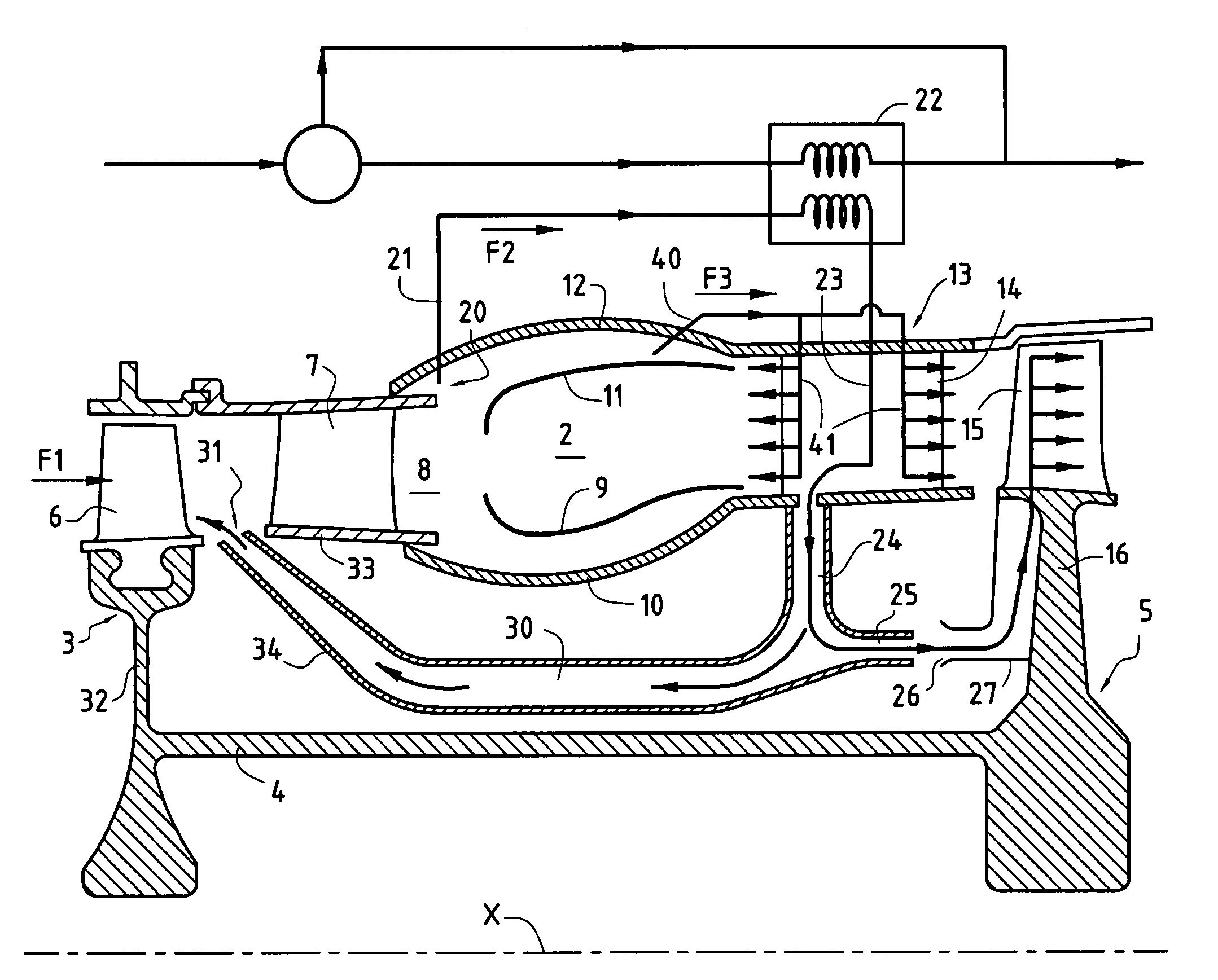
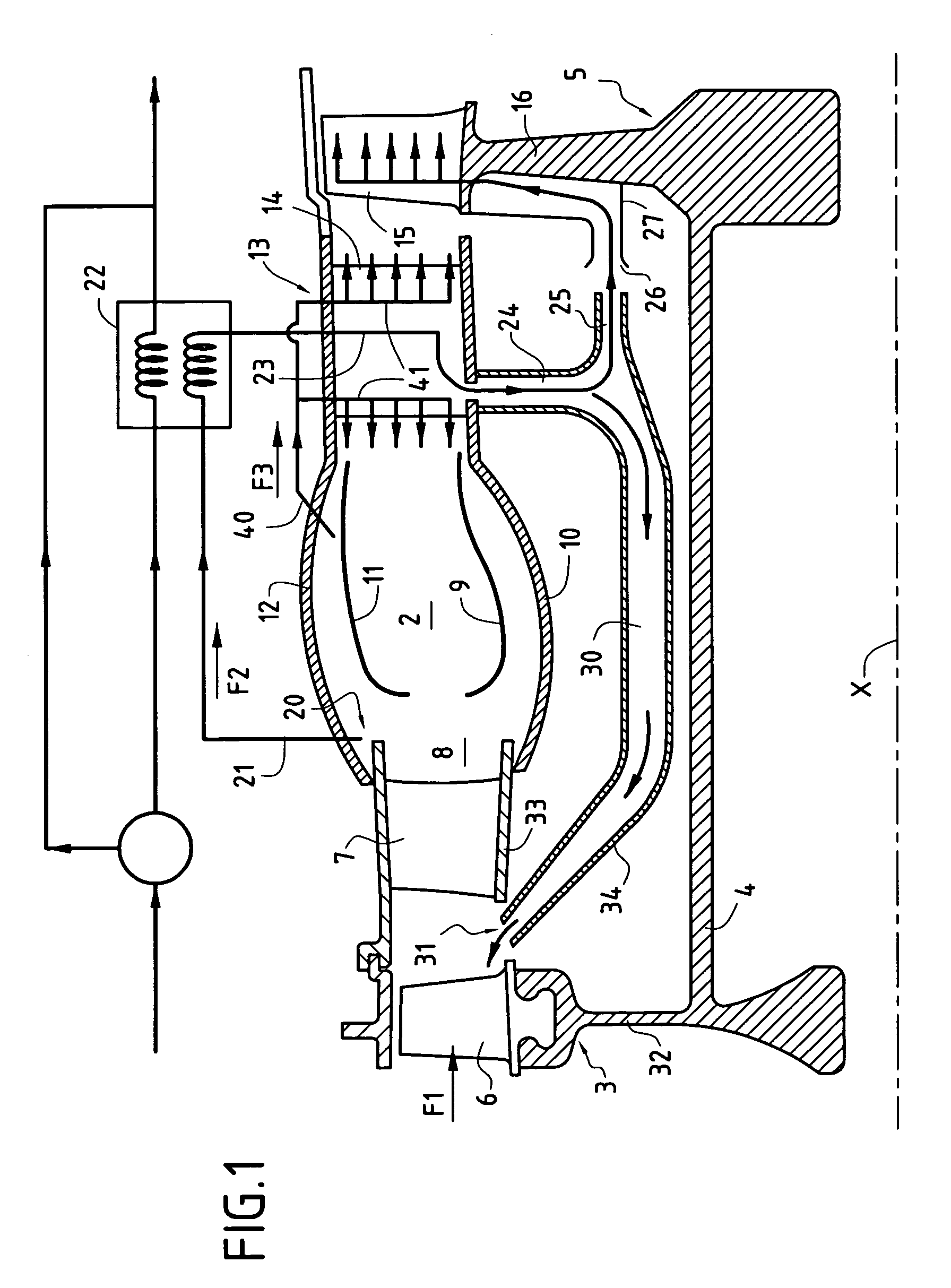
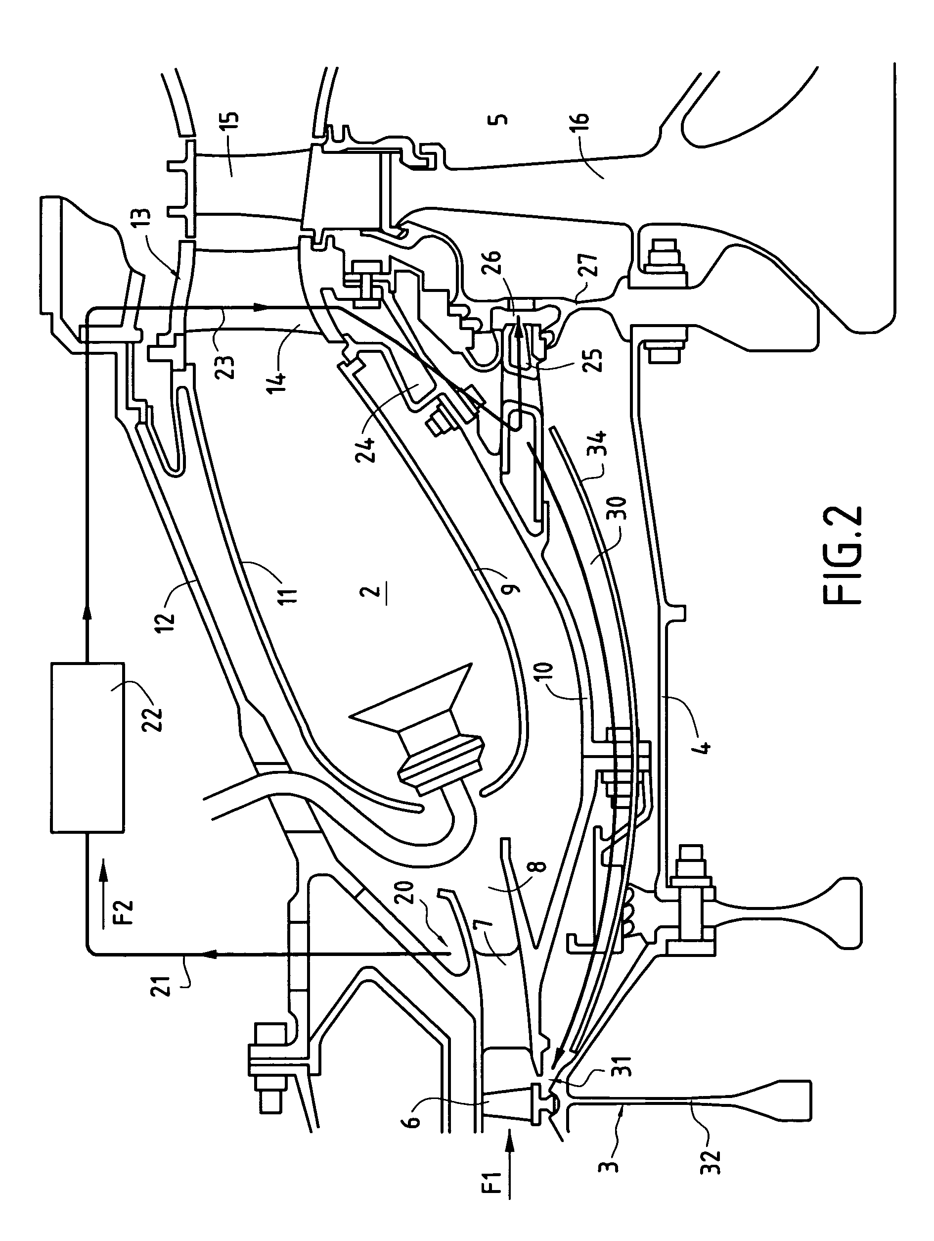
[0020]The drawings show a portion of the high pressure spool of a turbojet of axis X, which comprises, upstream from an annular combustion chamber 2, a rotor of a compressor 3 (only the last stage of which is shown), which rotor is driven by means of a shaft 4 by a rotor of a turbine 5 (with only the first moving wheel of the turbine being shown).

[0021]In traditional manner, the last stage of the compressor rotor 3 carries a ring of moving blades 6 serving to compress the primary flow F1 flowing along an annular channel, and disposed upstream from a stationary ring of rectifying blades 7 which deliver the primary flow F1 into the combustion chamber 2 via a diffuser 8.

[0022]The annular combustion chamber 2 is defined by a radially-inner wall 9 situated radially outside an inner casing 10, and by a radially-outer wall 11 situated radially inside an outer casing 12.

[0023]The walls 9 and 11 are connected to the inner and outer casings 10 and 12 respectively at the inlet to a distributor...


PUM


Abstract

The invention relates to a method of supplying cooling air to the hot portions of a turbojet that comprises, from upstream to downstream: a compressor; a diffuser; a combustion chamber; a distributor; and a turbine driving said compressor, in which method a flow of air is bled from the flow of air delivered by the compressor, the bled-off flow is cooled in a heat exchanger situated radially outside the combustion chamber, and is then directed radially inwards via the stationary blades of the distributor and used for cooling the moving wheel of the turbine, the method wherein the flow of cooling air is bled from the zone of the end of the combustion chamber that surrounds the diffuser, and wherein the stationary blades of the distributor are also cooled by a second flow of air bled from the diffuser.

Description

[0001]The invention relates to a field of turbojets, and more precisely to the field of cooling the hottest elements of turbojets.BACKGROUND OF THE INVENTION[0002]Considerable progress has been made in turbojets in terms of reducing fuel consumption and increasing specific power, by improving the thermodynamic cycle.[0003]This improvement has been obtained in particular by increasing the pressure of the air fed to the combustion chamber, and by increasing the temperature at the inlet to the turbine.[0004]However, increasing temperature and the inlet to the turbine requires the blades of the distributor and the blades of the first stage of the high pressure turbine that drives the high pressure compressor to be cooled energetically, since said blades are parts that are subjected to the highest temperatures and to high levels of stress. Such cooling is generally performed by bleeding a flow of air under pressure from the last stage of the high pressure compressor and passing it throug...

Claims


Application Information

Patent Timeline
Patent Type & Authority Patents(United States)
IPC IPC(8): F02C7/12F01D5/08F01D5/18F01D25/12F02C1/00F02C7/18F04D29/58
CPCF01D25/12F02C7/185F04D29/584F05D2260/213Y02T50/60
Inventor PALMISANO, LAURENTJABLONSKI, LAURENT
Owner SN DETUDE & DE CONSTR DE MOTEURS DAVIATION S N E C M A
Why Eureka
Try Eureka