Compression tool jawarm member

a technology of compression tool and jawarm member, which is applied in the direction of shaping tools, forging/pressing/hammering apparatus, forging presses, etc., can solve the problems of reducing the structural complexity of the jawarm member and the jaw set using such strapped members, and reducing the so as to improve the stability and stability of the jawarm member. , the failure of the jawarm member and the jaw set is still unpredictabl

Active Publication Date: 2006-02-21
EMERSON ELECTRIC CO
View PDF18 Cites 30 Cited by
  • Summary
  • Abstract
  • Description
  • Claims
  • Application Information

AI Technical Summary

Benefits of technology

[0005]In accordance with the present invention, a jawarm is provided with a stress concentrator along the inner edge thereof and in the area of the jawarm which is under tension during use. The stress concentrator is structured and oriented relative to the inner and outer edges of the jawarm to provide a failure point at the inner edge for consistently initiating a fatigue crack at the failure point and fracture of the jaw member along a predictable path from the failure point toward the outer edge of the jawarm. Consistently, as used herein with respect to the failure point, means a single point along the inner side of a jawarm at which a fatigue crack will initially occur for each and every failure of a jawarm. Preferably, though not necessarily, a jawarm member provided with a stress concentrator in accordance with the invention can be produced so as to provide a hinge effect at the outer end of the line of fracture so as to maintain the parts of the jawarm on opposite sides of the line of fracture against total separation. It is also preferred, though not necessary, to locate and orient the stress concentrator relative to the inner edge and pivot pin opening through the jawarm so that the line of fracture is directed to the pin opening. This control of the fracture is of advantage in that the pin opening provides the terminal end for the fracture, whereby the portion of the jaw member between the pivot pin opening and outer edge provides a hinge effect. The pivot pin opening, as part of the fracture line, provides a more predictable reaction between the adjacent parts of the jawarm as they are displaced relative to the hinge area. Even if the hinge effect is not achieved, the pin opening provides predictability with respect to the reaction between the jaw parts in connection with failure across the outer portion of the jawarm.
[0008]It is accordingly an outstanding object of the present invention to provide a pivotal jawarm for a compression tool in which the location and direction of failure of the jawarm resulting from use is consistently predictable and controllable.
[0010]A further object is the provision of a jawarm of the foregoing character wherein the predictability and control of failure or breakage is achieved without compromising functions such as cam surface wear.
[0011]Still another object is the provision of a jawarm of the foregoing character which, in connection with failure thereof, can avoid the need for straps to keep the jawarm parts from completely separating from one another.

Problems solved by technology

Such failures most often result in separation of the jawarm members into distinct pieces and, in an effort to maintain the pieces together following breakage, strap arrangements have been incorporated in the jaw sets and fastened, for example, to the outer sides of the jawarm members so as to retain separated parts of a jaw member in the jaw set environment following a failure.
The strap approach to parts retention is expensive and renders the jawarm members as well as the jaw set using such strapped members structurally complex.
However, the location of failure was still unpredictable in that failures in from about 14% to 25% of each of the different sizes of jawarms tested occurred at the mounting pin clearance recess and across the jawarm arm to the outer side thereof.
Moreover, in most of the jawarms tested, the failure at the mounting pin clearance resulted in breakage of the arm into separate pieces.
Accordingly, there was no consistency with regard either to predictability of the location of jaw failure or control of the point of failure along the jawarm and direction of the line of fracture from the point of failure.

Method used


Image

  • Compression tool jawarm member
  • Compression tool jawarm member
  • Compression tool jawarm member

Examples


Embodiment Construction

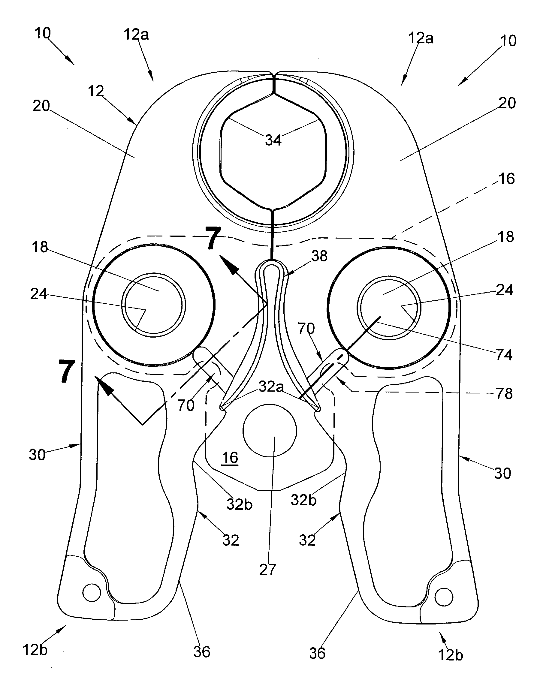
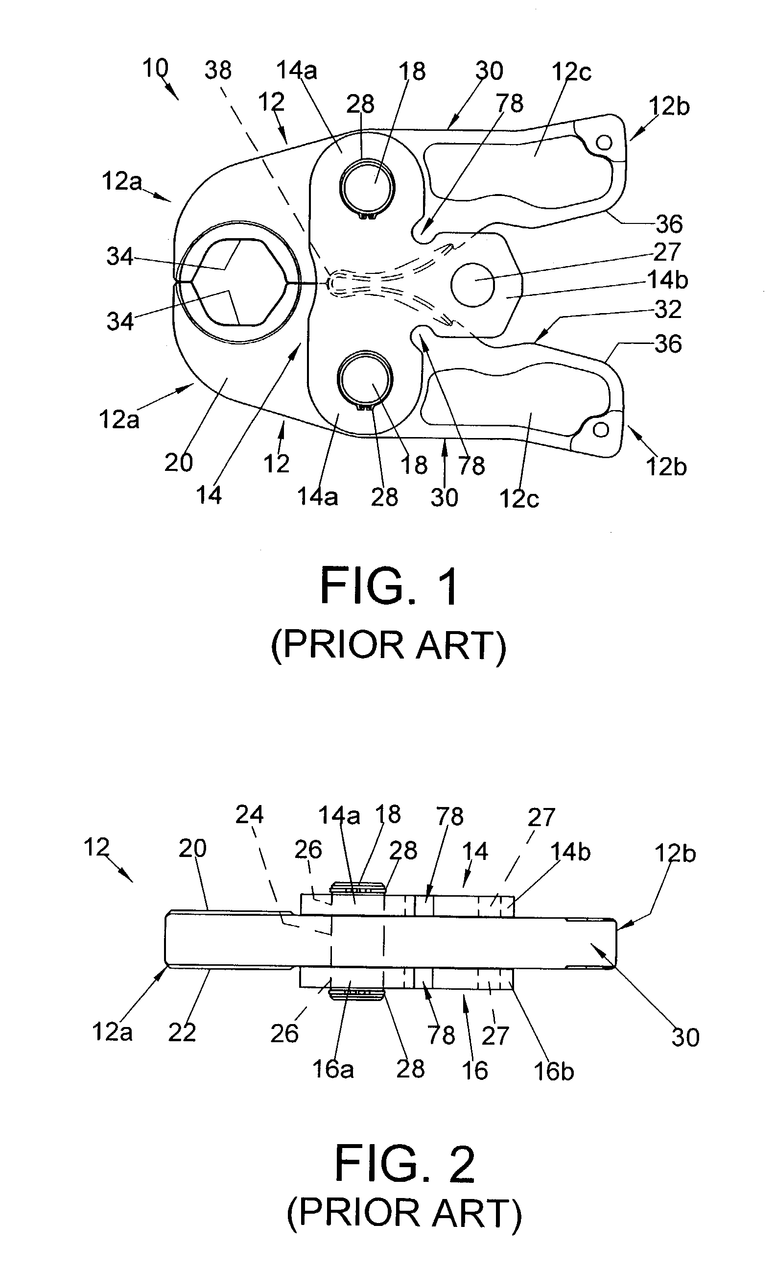
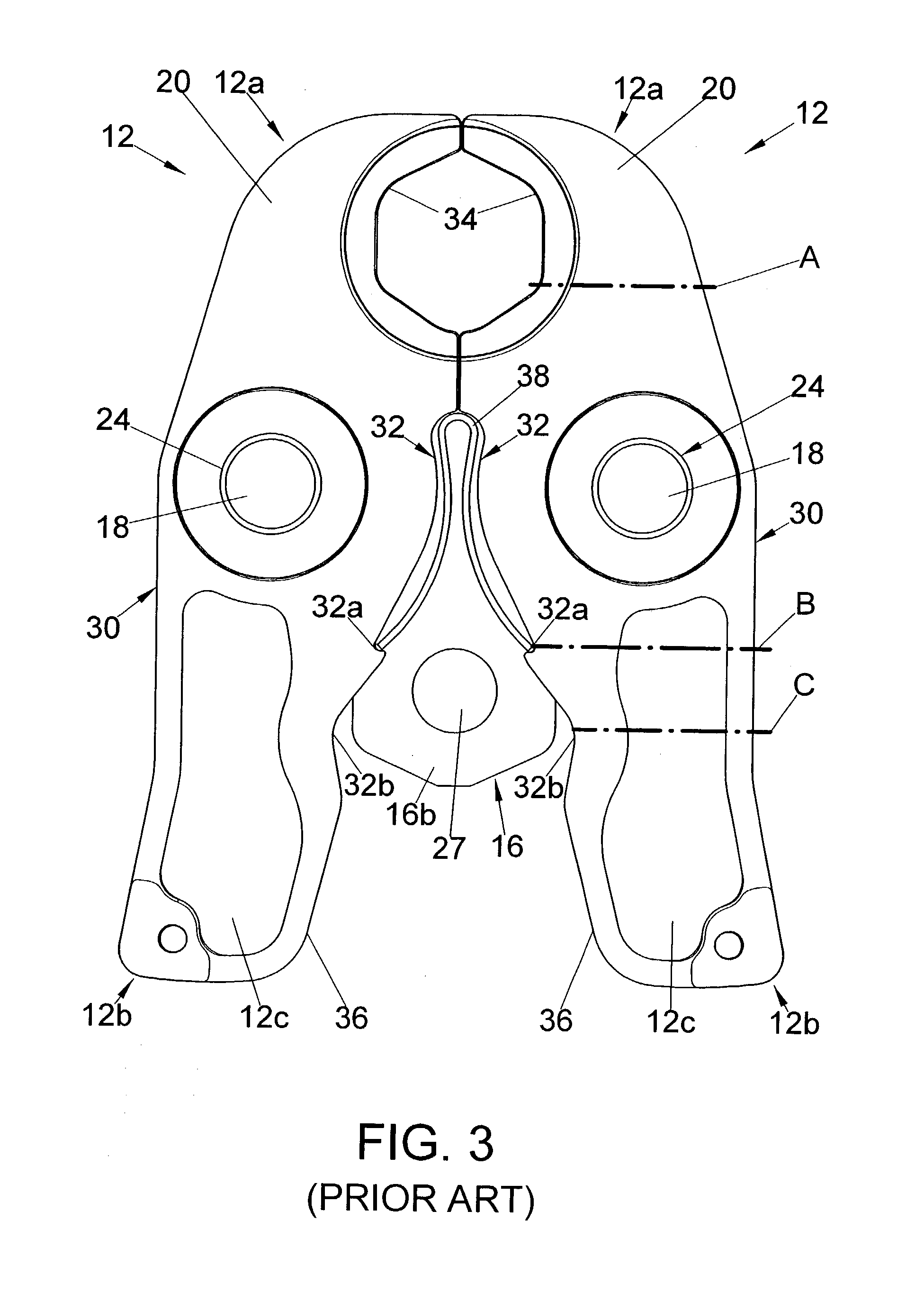
[0023]Referring now in greater detail to the drawings, wherein the showings are for the purpose of illustrating preferred embodiments of the invention only, and not for the purpose of limiting the invention, FIGS. 1–3 illustrate a prior art jaw set 10 comprising a pair of jawarm members 12 mounted, in the orientation shown in FIGS. 1–3 between top and bottom side plates 14 and 16, respectively, by a corresponding pivot or bearing pin 18. More particularly in this respect, each of the jawarm members 12 has a top side 20 and a bottom side 22 and a pin opening 24 therethrough for receiving the corresponding pin 18. Side plates 14 and 16 are generally T-shaped and include laterally opposite sides 14a and 16a, respectively, which are provided with aligned holes 26 for receiving the outer ends of the corresponding pin 18. Side plates 14 and 16 further include rear ends 14b and 16b, respectively, which are provided with aligned openings 27 therethrough which are adapted to receive a mounti...


PUM

PropertyMeasurementUnit
temperatureaaaaaaaaaa
stressaaaaaaaaaa
depthaaaaaaaaaa

Abstract

A pivotal jawarm for a compression tool has opposite sides, a pivot pin opening therethrough, longitudinally opposite ends on longitudinally opposite sides of the opening, and inner and outer edges between the ends and on laterally opposite sides of the opening. A stress concentrator comprising aligned recesses in the opposite sides of the jawarm extends from the inner edge toward the pivot pin opening and provides a failure point at the inner edge for consistently initiating a fatigue crack at the failure point and fracture of the jawarm from the failure point to the pivot pin opening.

Description

BACKGROUND OF THE INVENTION[0001]This invention relates to the art of compression tools for joining pipes and couplings and, more particularly, to an improved pivotal jawarm member for a compression tool.[0002]Compression tools for joining tubes or pipes and coupling components are well known as shown, for example, in U.S. Pat. No. 6,035,775 to Nghiem. Such tools include a compression jaw set removably mounted on a drive mechanism by which the jawarms of the set are displaced into compression about a pipe and coupling to join the latter. More particularly, the jaw set is comprised of a pair of jawarm members pivotally mounted between a pair of side plates and having inwardly open opposed jaw recesses at one end and laterally inwardly facing cam surfaces at the opposite ends. The jawarms are pivotal about pins located in openings through the jawarms between the opposite ends thereof, and the jaw set is mountable on the drive mechanism by means of the side plates and at a location rel...

Claims


Application Information

Patent Timeline
Patent Type & Authority Patents(United States)
IPC IPC(8): B21D39/00B23P19/04B25B27/10
CPCB25B27/10
Inventor HAMM, JAMES E.SMOLIK, JAMES E.SMITH, JASON M.
Owner EMERSON ELECTRIC CO
Why Eureka
Try Eureka