

Pleated shade cut-off method and apparatus
- Summary
- Abstract
- Description
- Claims
- Application Information
AI Technical Summary
Benefits of technology
Problems solved by technology
Method used
Image

Examples
Embodiment Construction
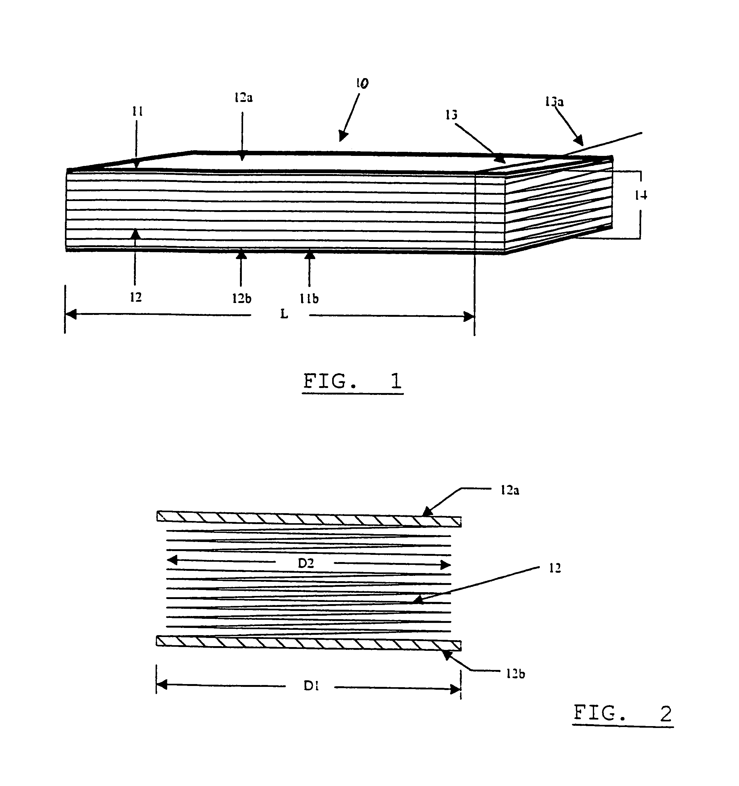
[0033]In the drawings, a typical window shade longitudinally i.e. widthwise extending assembly is shown at 10, and includes a shade 11 in the form of pleats in a stack 12, and retained vertically between upper and lower slats 12a and 12b. See FIGS. 1 and 2. It is desired to cut the assembly, as for example at a selected mark point 13, in a plane 13a normal to the assembly axis 14, corresponding to desired width L of the shade. (Shade “width” is in the elongation direction of the shade). The shade folded pleats may consist of plastic (synthetic resinous) material or paper, and the slats may consist of wood, plastic or metal.
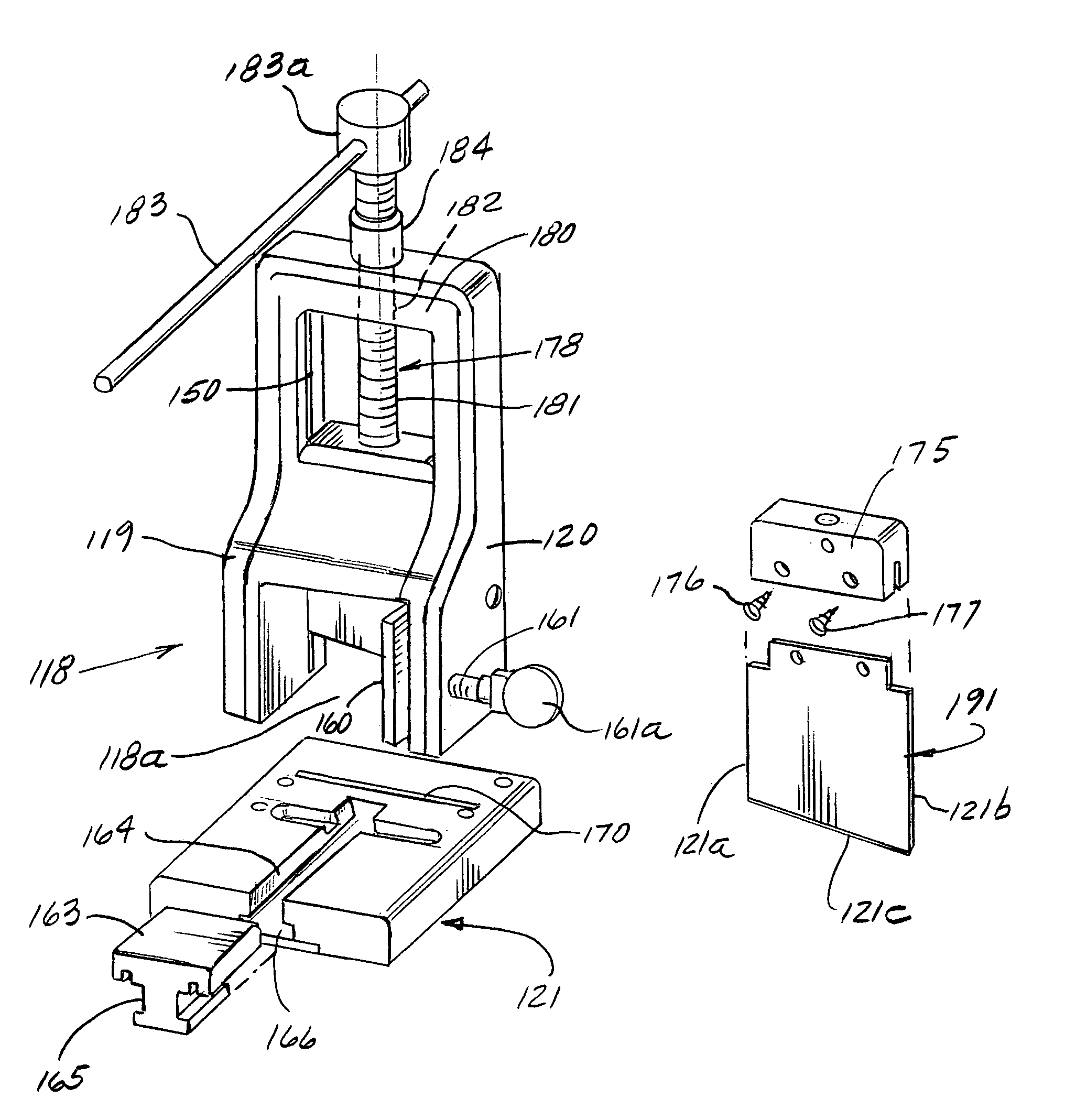
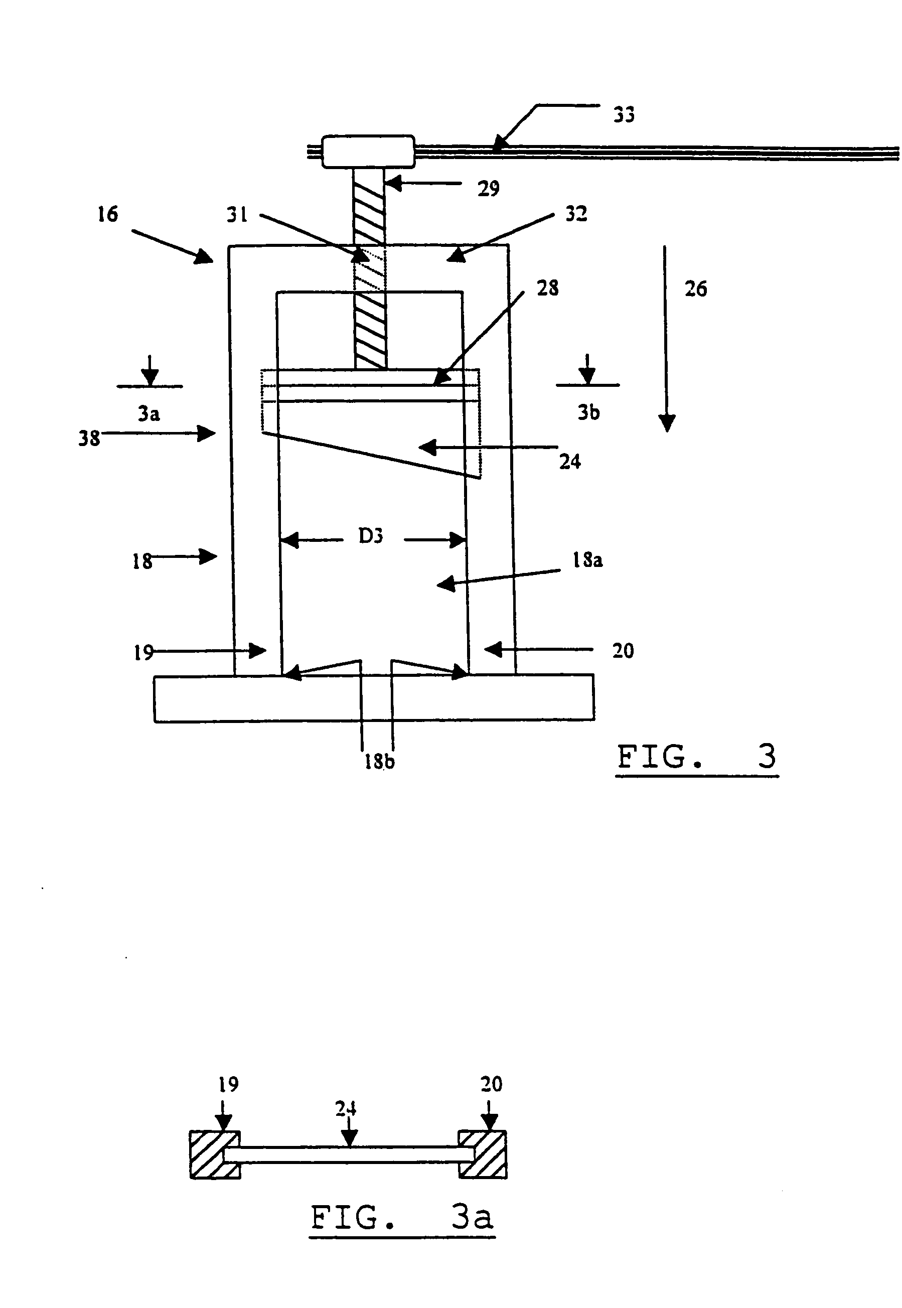
[0034]In accordance with the invention, preferred apparatus 16 is provided for severing to selected width the assembly 10. That apparatus as seen in FIG. 3 includes a holder, as for example the holder seen at 18, for supporting the shade assembly during progressive cutting, to be described. Holder 18 defines U-shaped channel 18a with lower corners 18b, to receive ...
PUM
| Property | Measurement | Unit |
|---|---|---|
| Angle | aaaaa | aaaaa |
| Angle | aaaaa | aaaaa |
| Length | aaaaa | aaaaa |
Abstract
Description
Claims
Application Information