Container comprising an electrically driven interlocking mechanism

a technology of interlocking mechanism and container, which is applied in the direction of latching fasteners, buckles, transportation and packaging, etc., can solve the problems of limited use and special problems of container spreaders, and achieve the effects of avoiding long repair times, ensuring the supply of electric current to the container, and minimizing the risk of injury to workers in the port or on the vessel

Inactive Publication Date: 2006-02-21
LEPUS VERMOGENSVERWALTUNG
View PDF11 Cites 16 Cited by
  • Summary
  • Abstract
  • Description
  • Claims
  • Application Information

AI Technical Summary

Benefits of technology

[0008]A further substantial advantage of the invention lies in the fact that the manual locking and lashing which was customary hitherto can be done away with, and therefore the risk of injury of the workers in the port or on the vessel can be minimized. Additional substantial costs savings will be obtained as a result.
[0009]According to a preferred embodiment, the container exhibits a frame structure design, of which at least one frame part has at least one water-tight closable opening. The purpose of this opening is that the locking mechanism secured in the corner which is designed as a hollow body, which according to a further preferred embodiment is designed as a module, can be taken out of the corner and reinserted. In this way, defective parts can be immediately replaced and long repair times avoided. The container will constantly be kept ready for use.
[0010]If, according to a further embodiment, the hollow bodies are connected to their adjacent frame parts in a releasable manner, openings in the frame parts can be used to connect the frame parts to the adjacent hollow bodies from the inside. Inasmuch as parts of the device according to the invention are located in the frame parts, access to these parts is guaranteed, so that both construction as well as maintenance are possible without any problem.
[0011]According to a further advantageous embodiment, the container exhibits means of accepting and forwarding electrical energy. In this way, the supply of electric current to the container can be guaranteed. This is particularly necessary for the operation of the locking device and the control unit.
[0012]This control unit controls the introduction of electricity into the locking mechanism and the onward conveyance of electricity to a discharge location in the area of the lower hollow body, by means of which electricity can be passed on into the next lower container. In addition, the control unit accepts the signals which, according to a further preferred embodiment, are transmitted to it by the signal generator, which is in contact with sensors. The intention of these signals is to indicate to the crane driver the position in which the locking mechanism is located. Moreover, according to a preferred embodiment data like the year of construction, the service interval or the load of the container as well as its places of departure and arrival or its location are stored in the control unit and may be recalled on demand.
[0013]To advantage, the electrically driven locking mechanism comprises a cylinder, in the wall of which a longitudinal cut-out is located, which has approximately the appearance of a V rotated through 90°. A bolt engages into this cut-out, which is secured to the locking bar. This link drive arrangement allows for a rotation of the locking mechanism, and therefore the locking of the containers to one another.

Problems solved by technology

The advantage of such container spreaders is limited, however, since on the one hand only the small containers (20 feet) can be accommodated, while on the other hand two such containers must stand one behind the other and the possibility of use only pertains in situations in which there is sufficient deposition space.
The situation becomes particularly problematic if several containers stacked on top of one another must be interlocked, such as is necessary in particular with ships' loads or in container terminals.
This is time-consuming and, because of the risk of injury when applying the connecting and locking elements, also dangerous.

Method used


Image

  • Container comprising an electrically driven interlocking mechanism
  • Container comprising an electrically driven interlocking mechanism
  • Container comprising an electrically driven interlocking mechanism

Examples


Embodiment Construction

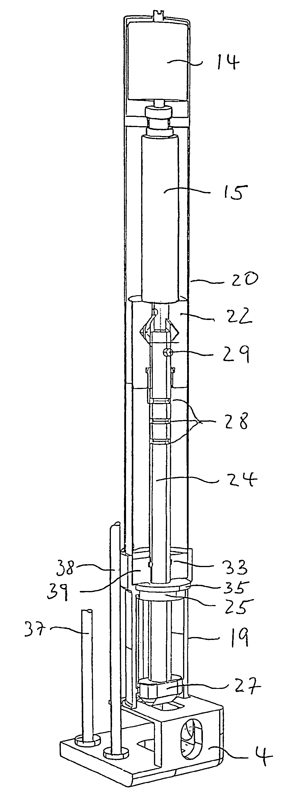
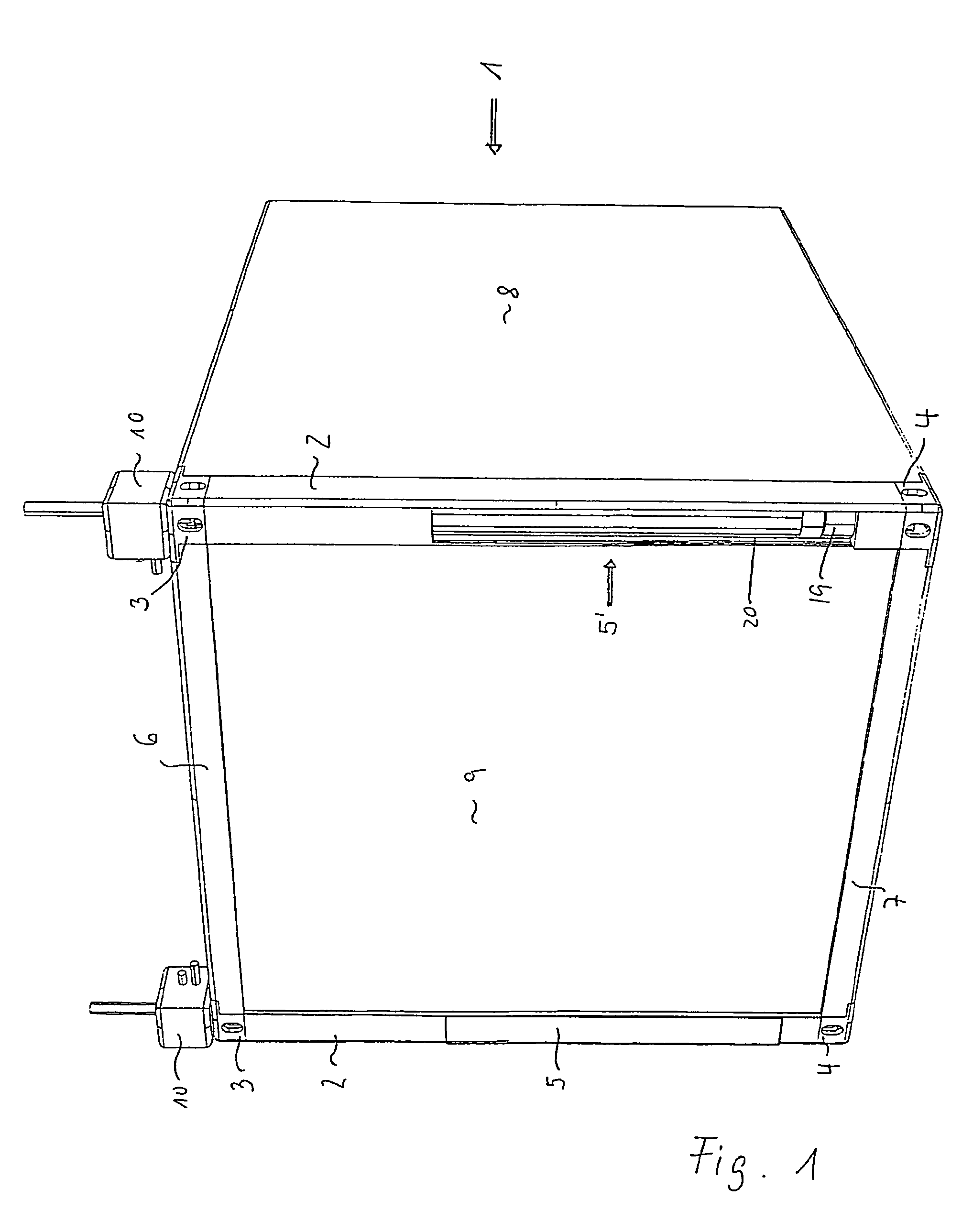
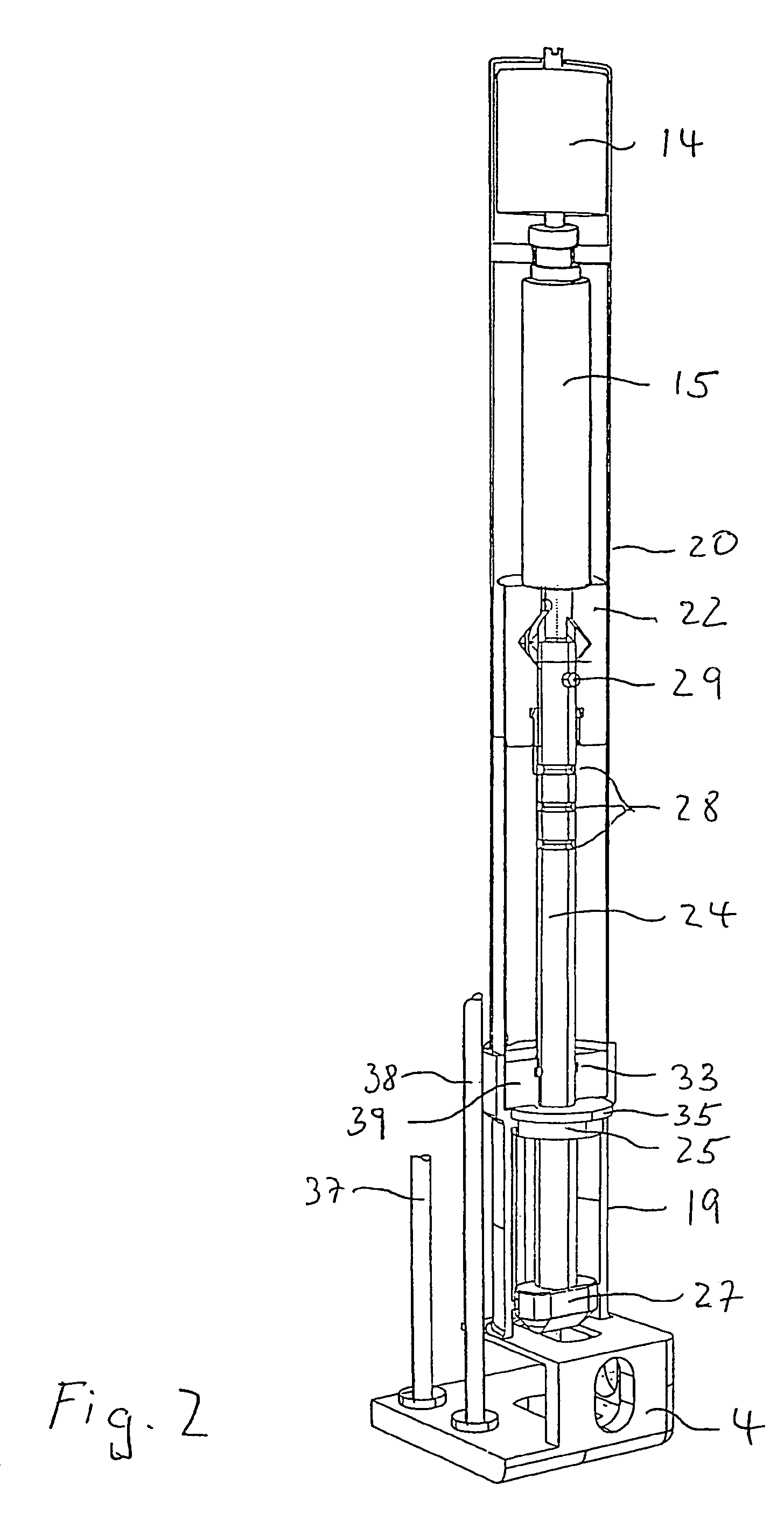
[0020]FIG. 1 represents a container (1) in a part view. It exhibits corners (2), on the upper end of which is located a locking housing (3), referred to hereinafter as a casting, and on the lower end of which a casting (4) is located. The container corners (2) are hollow on the inside and exhibit closure elements (5) at their lower area. This closure element is represented, for the purposes of the representation, as lying on the outside of the container corner. Expediently, the closure element is, however, located on the inside of the container and is guided over the corner, so that good accessibility is provided into the interior of the container corner. Thanks to this positioning, the interior of the container corner is protected against dirt and water. The closure element is bolted to the corner of the container by means of a water-tight and dust-tight seal, not represented here in any greater detail.

[0021]The upper castings are connected to one another by means of upper transver...


PUM


Abstract

A container having corner regions with hollow bodies is provided. Locking devices are provided that are received in the corner regions. Electrically driven, rotatable and displaceable locking mechanisms are respectively disposed in corners of the container. For a lower region of each locking mechanism, a locking member is provided that is adapted to engage in corresponding hollow bodies, disposed on upper corner regions of a comparable container disposed there below and adapted to receive locking devices, for interlocking the containers, sensors and signal emitters are disposed in the container for indicating a respective position of one of the locking mechanisms in a corner of the container.

Description

BACKGROUND OF THE INVENTION[0001]The invention relates to containers with electrically driven locking mechanisms, and in particular to shipping containers. It is, however, applicable to all containers in the same manner, irrespective of size and shape, on the outer walls of which hollow bodies are provided for the accommodation of locking devices. The invention is explained hereinafter in greater detail by way of the example of a shipping container.[0002]The transport of freight goods is effected nowadays worldwide preponderantly by the use of standardized containers. The containers are deposited at the loading location, loaded there, and then loaded onto a vehicle (road or rail vehicle), if appropriate conveyed to a harbor or airport, there loaded onto a ship or aircraft, and therefore interlocked and lashed together with other containers in order to provide secure transport, unlocked and released from lashings again at the place of arrival, and loaded onto a vehicle, brought to th...

Claims


Application Information

Patent Timeline
Patent Type & Authority Patents(United States)
IPC IPC(8): B66C1/66A45C13/10B65D90/00
CPCB65D90/0013Y10T24/28B61D5/08B65D88/12
Inventor HASE, STEPHANCÖNEN, GÖTZ
Owner LEPUS VERMOGENSVERWALTUNG
Why Eureka
Try Eureka