Electric operation apparatus

a technology of operation apparatus and electric motor, which is applied in the field of electric operation apparatus, can solve the problems of tissue degeneration, excessively slow tissue degeneration, and more difficult for a specialist to terminate treatmen

Inactive Publication Date: 2006-02-21
OLYMPUS CORP
View PDF27 Cites 268 Cited by
  • Summary
  • Abstract
  • Description
  • Claims
  • Application Information

AI Technical Summary

Benefits of technology

[0016]An object of the present invention, which was accomplished in view of the above-described situation, is to provide an electric operation apparatus and an output control method that make it possible to consistently verify coagulation completion and to prevent tissue from carbonizing or adhering to electrodes irrespective of the size of the contact area between the tissue and the electrodes.
[0017]Another object of the present invention is to provide an electric operation apparatus and an output control method that allow the tissue degeneration rate to be kept within a range readily discernible by the specialist and the coagulation state to be easily identifiable irrespective of the size of the contact area between the tissue and the electrodes.
[0018]Yet another object of the present invention is to provide an electric operation apparatus and an output control method that prevent tissue from carbonizing or adhering to electrodes and that allow coagulation and other types of therapeutic treatments to be consistently performed even with a variable contact area.

Problems solved by technology

However, the small size of the contact area between the tissue and the electrodes speeds up tissue degeneration and makes it more difficult for a specialist to terminate treatment once the desired coagulation state has been achieved.
Another drawback is that a large contact area results in excessively slow tissue degeneration, and takes too long to obtain the desired coagulation state.
H8-98845 and H10-225462 are disadvantageous in that when a small contact area is formed between the tissue and the electrodes, measurement results concerning electric current and the like become unstable and coagulation is sometimes considered to be complete even though in reality it is not.

Method used


Image

  • Electric operation apparatus
  • Electric operation apparatus
  • Electric operation apparatus

Examples


first embodiment

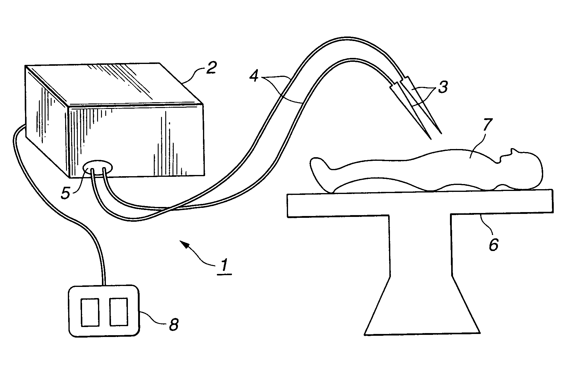
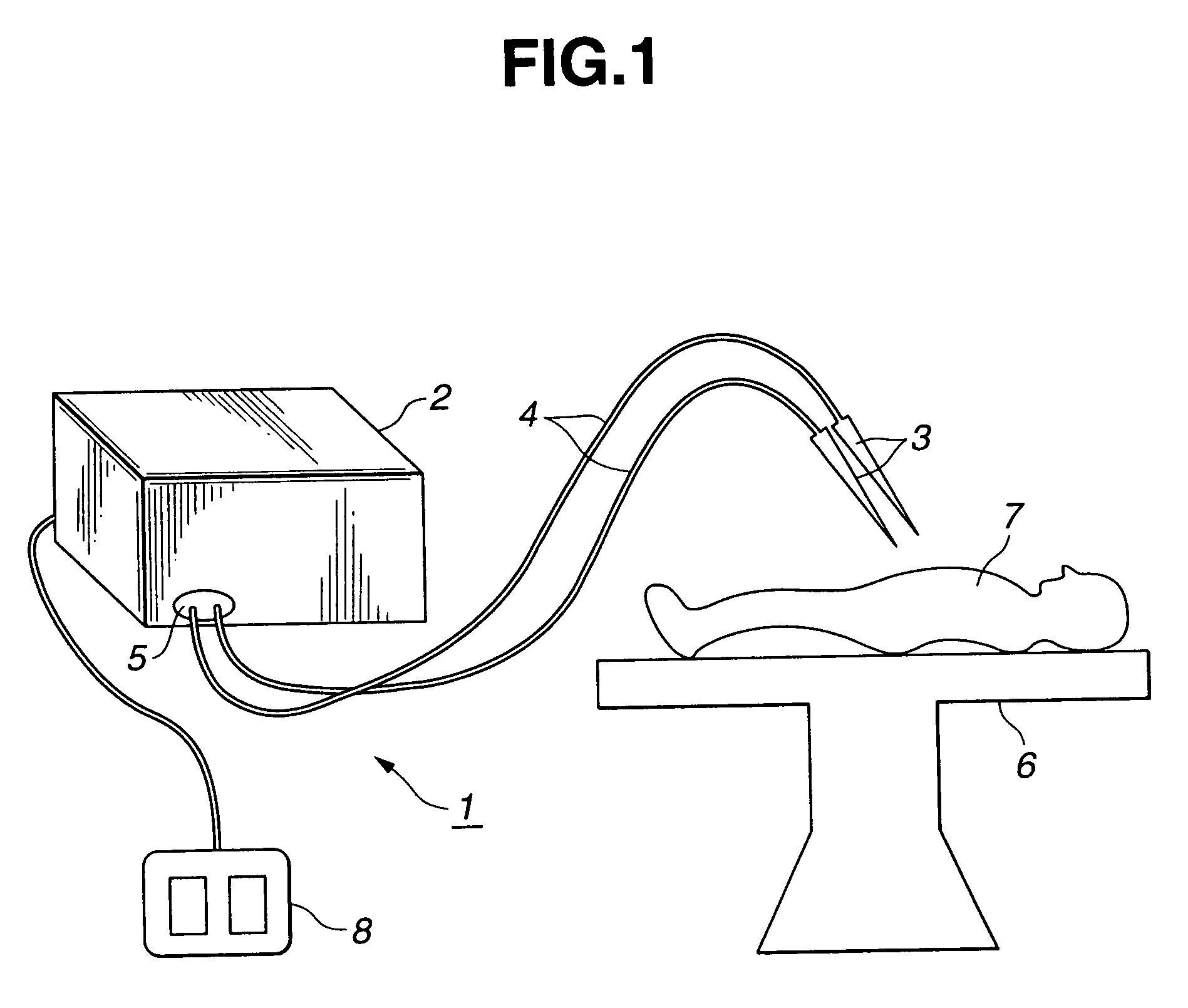
[0046]As can be seen in FIG. 1, the high frequency cauterizing unit 1 pertaining to the inventive electric operation apparatus comprises a high frequency cauterizing power supply unit 2 for feeding high frequency cauterizing electric power, wherein the high frequency cauterizing power supply unit 2 is connected by a connector 5 to connector cables 4 whose tips are provided with electrodes 3 (treatment means). High frequency cauterizing electric power for therapeutic purposes is fed via these electrodes 3 to a patient 7 on a bed 6 to perform a therapeutic treatment (surgical treatment).

[0047]A foot switch 8 is an example of a device designed for switching on and off the high frequency cauterizing electric power and connected to the high frequency cauterizing power supply unit 2. The electrodes 3 may be single electrodes or multiple electrodes.

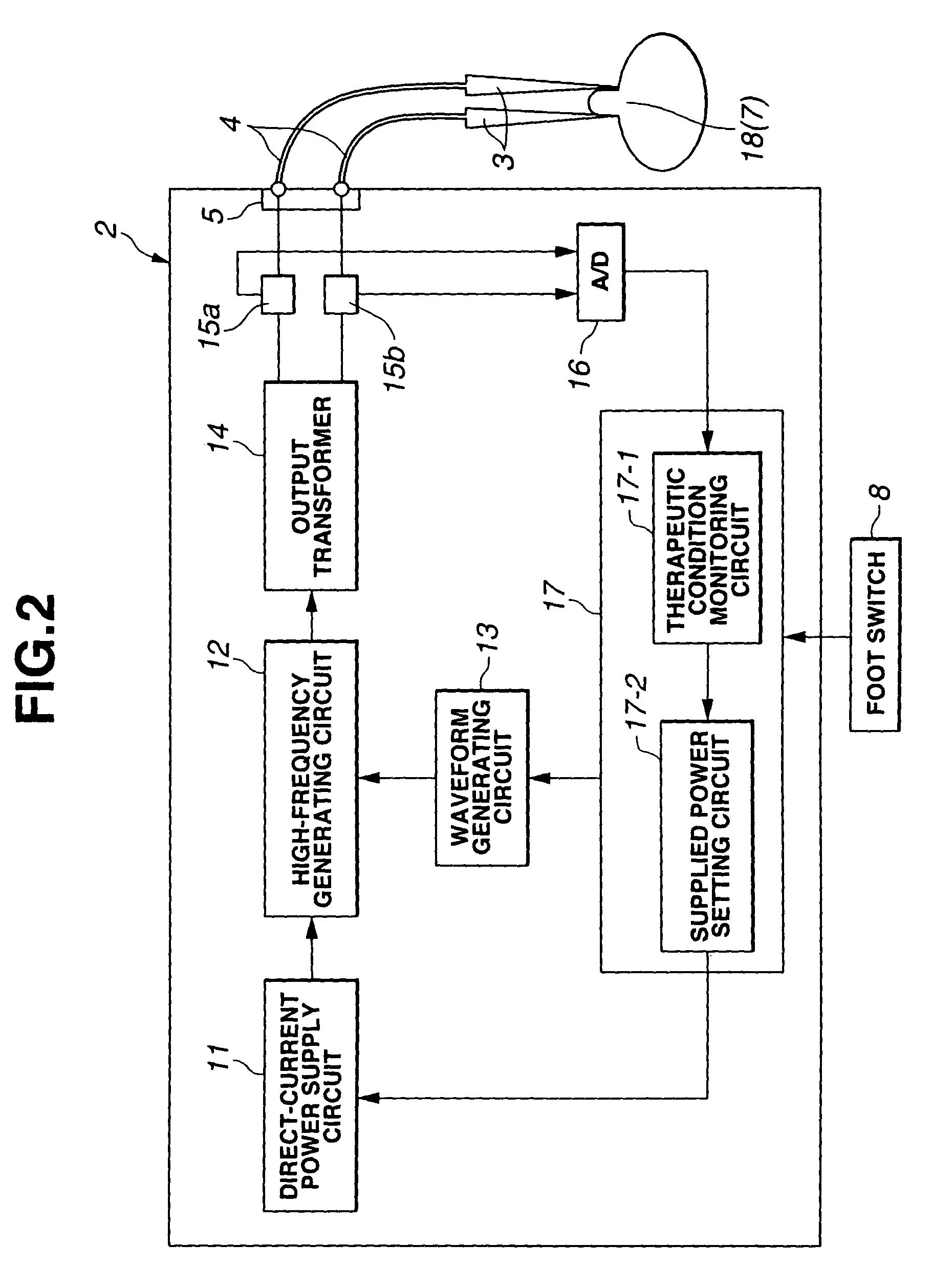
[0048]As can be seen in FIG. 2, the high frequency cauterizing power supply unit 2 has a direct current power supply circuit 11 connected to a ...

second embodiment

[0091]A second embodiment will now be described.

[0092]The second embodiment of the present invention will now be described with reference to FIGS. 7 to 12. FIG. 7 is a block diagram depicting the structure of a high frequency cauterizing power supply unit. FIG. 8 is an expanded view of an electrode. FIG. 9 is a flow chart depicting the control steps performed by the control circuit in FIG. 7. FIG. 10 is a diagram illustrating the threshold value established in accordance with thickness. FIG. 11 is a diagram illustrating a specific example of the manner in which the set value of electric power and the impedance vary with time when a high frequency current is allowed to flow. FIG. 12 is a diagram illustrating the manner in which the value of electric power is set in accordance with the minimum impedance value.

[0093]The second embodiment is substantially similar in structure to the first embodiment. Consequently, the differences alone will be described, identical components will be des...

third embodiment

[0117]A third embodiment will now be described using FIGS. 1, 2, 13, 14, and 15.

[0118]FIG. 13 is a flow chart depicting the control flow of the control circuit in FIG. 2. FIG. 14 is a functional diagram illustrating a power control routine for monitoring the amount of time corresponding to variations in the electric current value of the high frequency current produced by the high frequency cauterizing power supply unit. FIG. 15 is a functional diagram illustrating an electric current control routine for monitoring the amount of time corresponding to variations in the electric current value of the high frequency current produced by the high frequency cauterizing power supply unit.

[0119]Overlapping portions will be omitted from the description because a description has already been given with reference to FIGS. 1 and 2. Here, the control circuit 17 monitors the digitized electric current data from the A / D converter circuit 16 over time (that is, monitors the amount of time correspondi...


PUM


Abstract

An electric operation apparatus including: a high frequency current generating circuit for feeding a high frequency current to electrodes; a direct power supply circuit for supplying variable electric power to the high frequency current generating circuit; a therapeutic condition monitoring circuit for monitoring a therapeutic condition brought about by the high frequency current on the basis of the high frequency current outputted by the high frequency electric current generating circuit; and a supplied power setting circuit for supplying a setting signal for supplied electric power to the power supply circuit on the basis of the monitoring results obtained by the therapeutic condition monitoring circuit.

Description

[0001]This is a continuation of application Ser. No. 09 / 727,876 filed on Dec. 1, 2000, now U.S. Pat. No. 6,635,057.[0002]This application claims benefit of Japanese Applications No. H11-343691 filed in Japan on Dec. 2, 1999 and No. H11-368189 filed on Dec. 24, 1999, the contents of which are incorporated by this reference.BACKGROUND OF THE INVENTION[0003]1. Field of the Invention[0004]The present invention relates to an electric operation apparatus, and more particularly to an electric operation apparatus and an output control method featuring a specific output control section for high frequency current.[0005]2. Description of the Related Art[0006]Electric knives and other types of electric operation apparatus are commonly used to incise or coagulate biological tissue, to stop bleeding, or to perform other procedures when internal or external surgery is conducted.[0007]Such an electric operation apparatus comprises a high frequency cauterizing power supply unit and a treatment means...

Claims


Application Information

Patent Timeline
Patent Type & Authority Patents(United States)
IPC IPC(8): A61B18/12
CPCA61B18/1206A61B2018/00702A61B2018/00875A61B2018/00827A61B2018/0072
Inventor HARANO, KENJIOHYAMA, MASAHIDEHIJII, KAZUYA
Owner OLYMPUS CORP
Why Eureka
Try Eureka