Artificial intervertebral disc device

a technology of artificial vertebrae and discs, which is applied in the field of artificial vertebrae disc devices, can solve the problems of affecting the stability of the disc, requiring more complex shapes, and prone to subsidence or fall around the ball, so as to reduce stress and wear that would otherwise occur in either of the interfaces, take up the compressive load, and minimize the interference with the shifting of the domes on the central spherical bearing portion

Inactive Publication Date: 2006-02-21
PIONEER SURGICAL TECH INC
View PDF180 Cites 122 Cited by
  • Summary
  • Abstract
  • Description
  • Claims
  • Application Information

AI Technical Summary

Benefits of technology

[0009]In one preferred form, the outer bearing portion has a body that includes radially inner surfaces adjacent the arcuate surfaces adapted or configured for allowing relative movement therebetween. The outer bearing shares the compressive loading generated between the vertebrae via upper and lower bearing surfaces or surface portions thereof so that the load is better distributed across the present artificial disc device minimizing localized forces thereon. With the provision of the outer bearing, the present device is well suited to avoid subsidence problems as could occur in prior devices having highly localized loading thereon.
[0010]The outer bearing or bearing assembly also may be constructed to provide improved shock absorption capabilities such as with an inner portion of the body that is softer than the harder outer portion. For example, an elastomeric layer of material can be employed between attached upper and lower bearing plates of the outer bearing, or the core layer of an annular portion and / or an inner ball bearing portion of the outer bearing can be of elastomeric or liquid gelled material. Manifestly, material combinations can also be employed to achieve desired shock absorption proportions. The outer bearing can further include a compression limiter so as to maintain proper tolerances between the outer bearing inner surfaces and the inner bearing surfaces in confronting relation therewith as the outer bearing is loaded. In this manner, the inner bearing maintains its freedom of movement despite the compressive loading that is being borne by the outer bearing, as will be described more fully hereinafter.
[0011]In one form, the artificial disc includes a central ball as the enlarged, central bearing portion with an annular body of the outer bearing extending thereabout. The upper and lower load bearing surfaces or surface portions of the outer bearing body preferably do not project axially as far toward the upper and lower vertebrae as the ball surface portions such as by having a larger radius of curvature than the radius of the ball. In other words, the load bearing surface portions have a more gradual curvature than the center bearing surface portions or for that matter they can have a flat configuration. This allows the enlarged ball to seat in the indents in the end plates for positioning the artificial disc securely between the vertebrae while the annular body is also effective in taking up the compressive loading between the upper and lower vertebrae.
[0012]In another form, the central bearing portion includes a pair of generally dome-shaped shell members that ride on a generally spherical inner bearing portion integral with the outer bearing portion for sliding thereover. In this regard, the inner bearing portion is integrally connected to the outer bearing portion via a circumferential web wall. The domes or shells are sized relative to the inner spherical bearing portion so that there are gap spaces between the peripheral edges of the domes and the web wall. The web wall positions the outer, annular load bearing portion such that interference with shifting of the domes on the central spherical bearing portion is minimized. Alternatively, snap-fitting the domes in place over the inner ball bearing portion could be employed; however, the above described loose-fitting construction is preferred to minimize binding of the dome shells under compressive load forces. In this manner, the domes can readily slide on the inner ball portion and, at the same time, the vertebral end plates or other vertebral surfaces in engagement with the arcuate surfaces of the domes can also shift with respect thereto to provide a bi-polar device with two interfaces that shift with respect to each other.
[0013]By having this bi-polar artificial disc construction, the stress and wear that would otherwise occur in either of the interfaces is decreased as one bearing interface can be shifting when the load on the other becomes too great. Lubricant can be provided between the dome shells and the inner bearing portion to reduce friction and wear therebetween. A seal ring attached adjacent or at the end edge of the shells for being carried therewith minimizes lubrication leakage while allowing the shells to slide over the spherical surface of the inner bearing portion in a low friction manner.

Problems solved by technology

However, devices such as these usually require special surface materials and / or surface treatments that allow for bone ingrowth for fixing the members to the vertebrae.
Moreover, these devices have had problems with migration where the intermediate bearing body shifts out from between the vertebrae, and thus generally require more complex shapes to form stops for resisting such disc shifting.
The ball approach, while effective to provide a good range of motion, tended to create subsidence problems.
In other words, since these ball implants were not of a size that enabled the load of the spine to be distributed evenly thereacross, the end plates tended to subside or fall around the ball.
However, these approaches are limited in their use to patients who have a substantially undamaged disc annulus.

Method used


Image

  • Artificial intervertebral disc device
  • Artificial intervertebral disc device
  • Artificial intervertebral disc device

Examples


Embodiment Construction

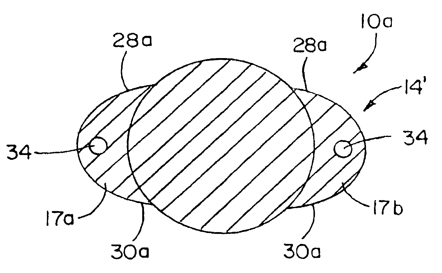
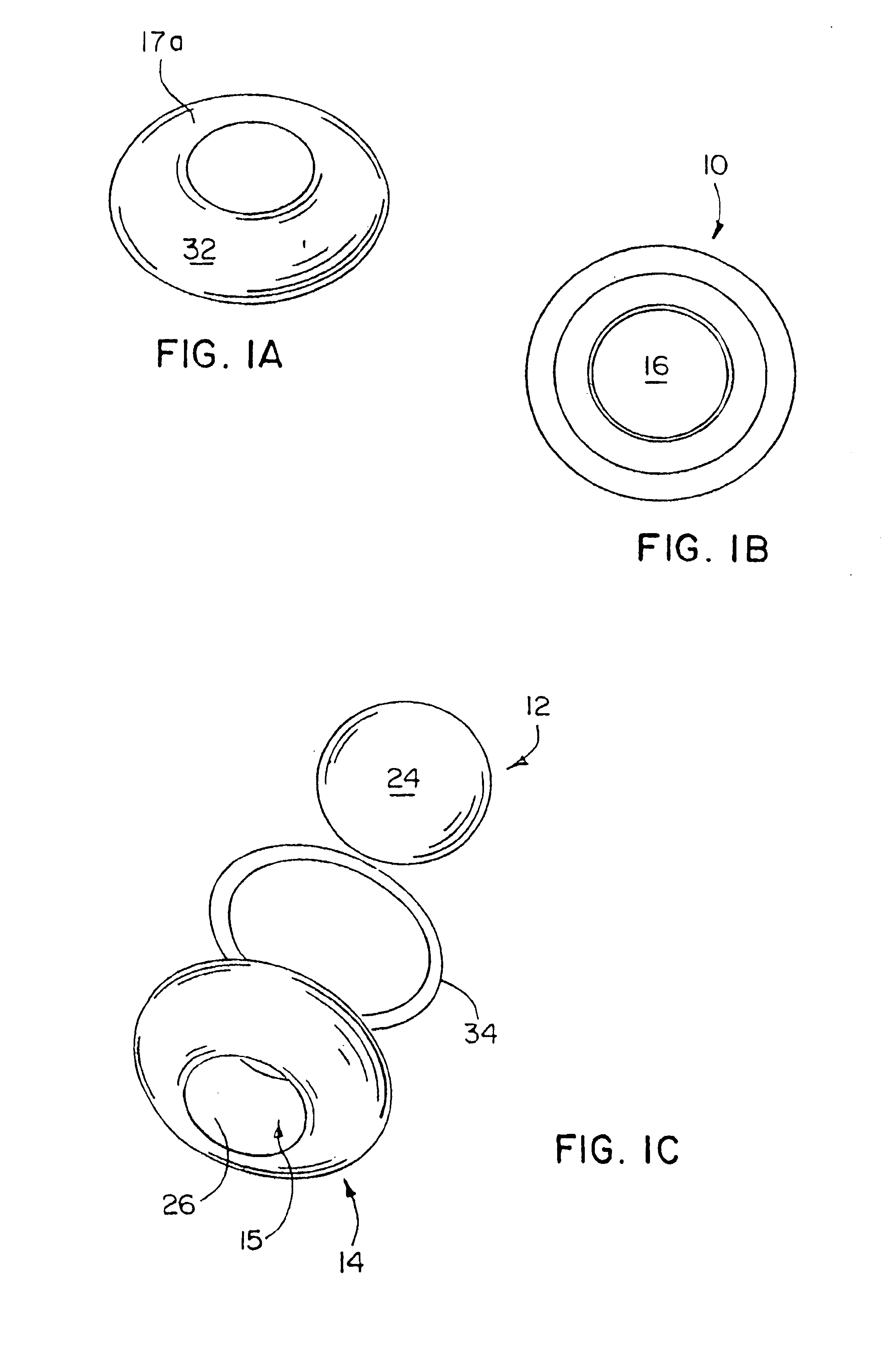
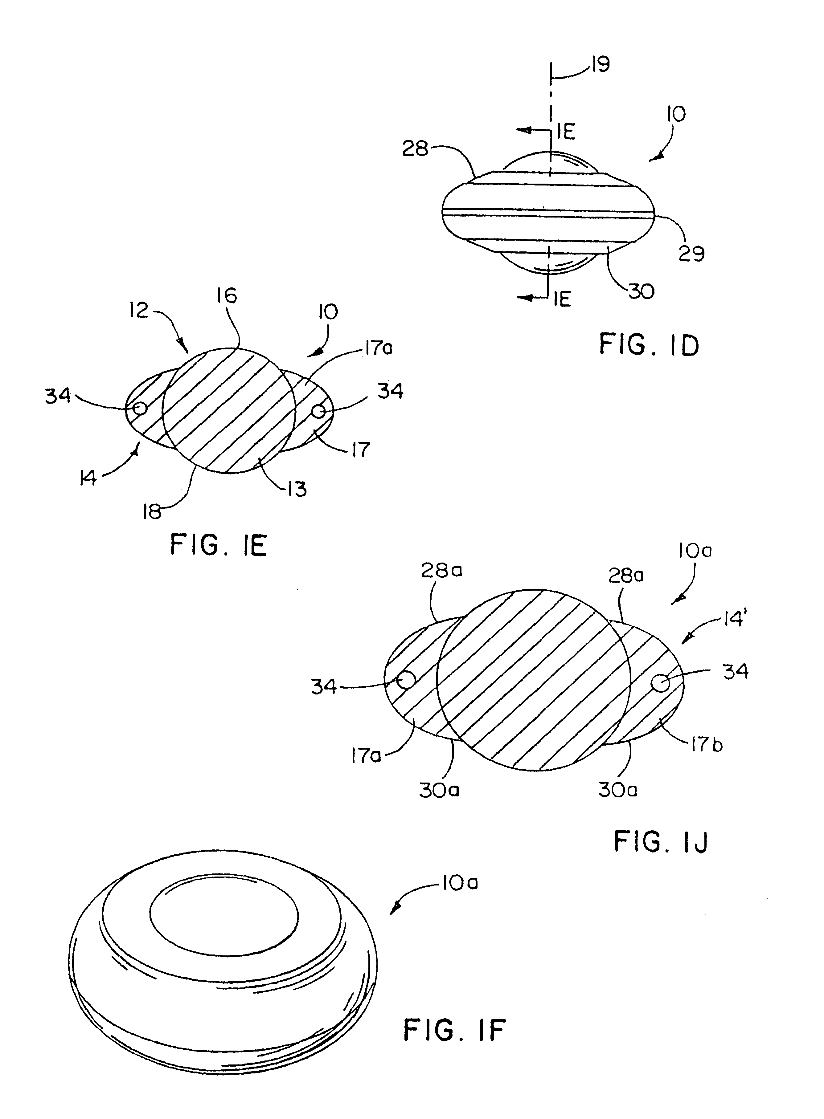
[0028]Referencing FIGS. 1A-1E, an artificial disc device 10 is shown which includes an enlarged, central bearing portion 12, and a substantially annular, outer bearing portion 14 having a through opening 15 in which the central bearing portion 12 is disposed. Herein, preferred shapes, configurations and material selections for the inner and outer bearing portions are set forth. However, in each case, these selections are not meant to be limiting as other selections that serve the purpose of the disc implant described herein are also contemplated. Likewise, several embodiments are disclosed that have structural features that can be implemented substantially interchangeably among the disc implants.

[0029]In the form illustrated in FIGS. 1A-1E, the central bearing 12 has an axially enlarged body 13 relative to the outer bearing 14 so that it generally includes arcuate surface portions 16 and 18 that project above and below the radially outer bearing portion 14 for engaging in indents in...


PUM

PropertyMeasurementUnit
thicknessaaaaaaaaaa
thicknessaaaaaaaaaa
distanceaaaaaaaaaa

Abstract

Artificial disc devices are disclosed that restore correct anatomical intervertebral spacing for damaged discs while maintaining a substantially normal range of biomechanical movement for the vertebrae between which they are implanted. The disc devices include center bearing and outer or annular bearing portions with the center bearing portion including generally axially extending locating surfaces which cooperate with the facing vertebral surfaces to resist migration. The outer bearing portion is for load bearing or load sharing with the center bearing portion and includes surfaces that extend radially toward the periphery of the vertebrae so that subsidence about the center bearing portion is minimized. Alternate forms of the disc devices include one with an axially enlarged center ball bearing having an annular ring bearing extending thereabout and another having upper and lower plate members with a central bumper member and a surrounding resilient annular member therebetween.

Description

[0001]This application claims the benefit of Provisional Application No. 60 / 382,758, filed May 23, 2002.BACKGROUND OF THE INVENTION[0002]Artificial disc technology has been employed to correct damaged spinal discs for relieving back pain and restoring or maintaining intervertebral spacing while attempting to minimize their constraining effects on the normal biomechanical movement of the spine. Two types of artificial discs have generally been employed: the artificial total disc which is designed to substitute for the entire disc, i.e. the annulus, nucleus and possibly the end plates as well; and the artificial nucleus where only the nucleus is replaced with the annulus and end plates remaining intact. The disc of the present invention is not intended to be limited to one or the other of the above types.[0003]A number of prior artificial disc devices include upper and lower members that are rigidly fixed to the adjacent upper and lower vertebrae. These fixed members sandwich a bearin...

Claims


Application Information

Patent Timeline
Patent Type & Authority Patents(United States)
IPC IPC(8): A61F2/44A61F2/00A61F2/30
CPCA61F2/442A61F2/4425A61F2/30742Y10S606/907A61F2002/30014A61F2002/30016A61F2002/30123A61F2002/302A61F2002/30242A61F2002/30245A61F2002/30299A61F2002/30311A61F2002/30331A61F2002/3039A61F2002/305A61F2002/30528A61F2002/30563A61F2002/30581A61F2002/30649A61F2002/30673A61F2002/30685A61F2002/30738A61F2002/30784A61F2002/30841A61F2002/30919A61F2002/30934A61F2002/30935A61F2002/443A61F2002/444A61F2220/0025A61F2220/0033A61F2230/0006A61F2230/0065A61F2230/0071A61F2230/0093A61F2250/0018A61F2250/0019A61F2310/00017A61F2310/00023A61F2310/00179A61F2310/00574A61F2/30965
Inventor SONGER, MATTHEW N.KILPELA, THOMAS S.JANOWSKI, BRIAN P.BERREVOETS, GREGORY A.GEPHART, MATTHEW P.
Owner PIONEER SURGICAL TECH INC
Why Eureka
Try Eureka