Method for manufacturing optical disc and method for transporting multi-layered optical disc

Inactive Publication Date: 2006-02-21
FUJIFILM HLDG CORP
View PDF5 Cites 2 Cited by
  • Summary
  • Abstract
  • Description
  • Claims
  • Application Information

AI Technical Summary

Benefits of technology

[0011]According to the foregoing description, it is an object of the invention to provide a method for manufacturing an optical disc, wherein the inner circumference to the outer circumference of the sh

Problems solved by technology

On the contrary, because the coma aberration created due to the tilt of the optical disc is increased in proportion to the third power of the NA, the tilt margin of the optical disc due to high NA is very small and the laser beam becomes dim due to a little tilt, so that it cannot achieve a high recording density.
When forming the cover layer by the sheet and the adhesive, it is very difficult to adhere the sheet, at least to within about 0.1 mm of the inner circumference of the sheet, to the disc substrate without damaging the quality of the optical disc, especially the appearance quality.
The ultraviolet curing adhesive overflowed from between the sheet and the disc substrate will be spun to the surface of the optical disc during the high speed rotation of the turn table, and this causes radiative blots when curing by the ultraviolet ray irradiation, resulting in the degradation of the appearance qua

Method used


Image

  • Method for manufacturing optical disc and method for transporting multi-layered optical disc
  • Method for manufacturing optical disc and method for transporting multi-layered optical disc
  • Method for manufacturing optical disc and method for transporting multi-layered optical disc

Examples


Example

Example 1

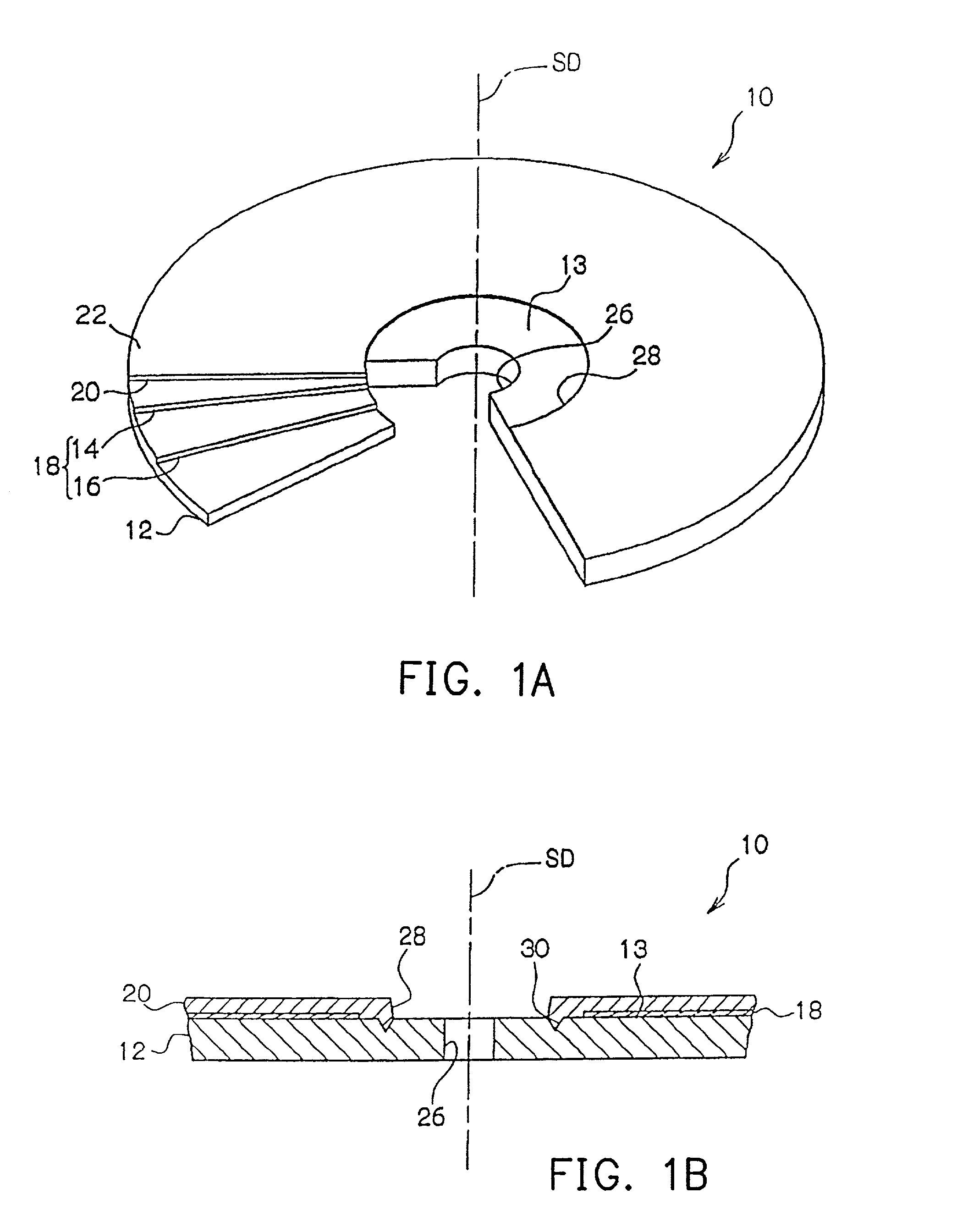
[0082]In the example 1, the disc substrate of the optical disc is formed by molding using a material of polycarbonate (PC), with a thickness of 1.2 mm, an outer radius of 120 mm. A guiding groove with a groove depth of 175 nm, a groove width of 500 nm and a track pitch of 1600 nm is formed on the recording surface of the disc substrate. In addition, a silver film with a thickness of 80 nm is used as a light reflection layer and is formed on the recording surface by a magnetron sputter. Furthermore, a thin film made of PET with a thickness of 62 μm is used as the sheet and is made to have the same surface shape as the disc substrate. In the example 1, on the disc substrate, a ring groove is formed on the inner side of the recording layer at the recording surface (inner ring groove). The inner ring groove is equivalent to the groove 30 of the optical disc 10 shown in FIGS. 1˜5.

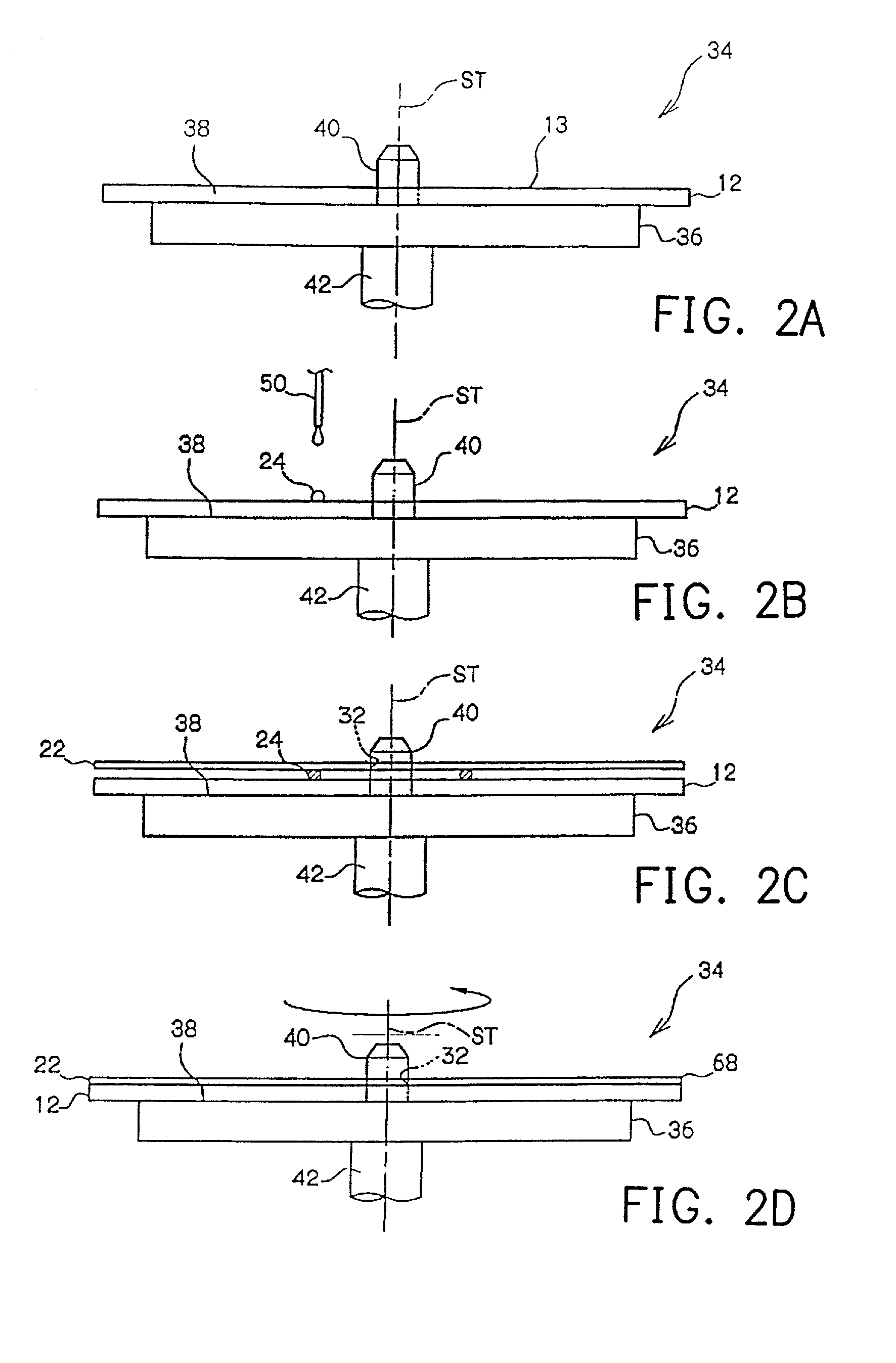
[0083]The above disc substrate is loaded onto the turntable of the spin coater. The turntable rotate...

Example

Comparison Example 1

[0085]In comparison example 1, except that no inner ring groove is formed on the recording surface of the disc substrate, is the same as example 1. In addition, the sheet has the same shape as the sheet that is cut to form the opening in example 1. In the comparison example 1, the disc substrate is loaded onto the turntable and the ultraviolet curing adhesive is supplied to the recording surface of the disc substrate. At this time, the amount and the supply position of the ultraviolet curing adhesive in the radial direction with respect to the disc substrate are the same as the example 1. The sheet is loaded onto the disc substrate through the ultraviolet curing adhesive, and the ultraviolet curing adhesive is pressed by the sheet to spread to the inner side. However, the ultraviolet curing adhesive is not uniformly spread to the inner side of the sheet. Next, the turntable of the spin coater is rotated under the same condition as the example 1, and the ultraviol...

Example

[0088]In the comparison example 2, except that no inner ring groove is formed on the recording surface of the disc substrate, others are the same as the example 1. In addition, the sheet has the same shape as the sheet that is cut to form the opening in the example 1. In the comparison example 2, the disc substrate is loaded onto the turntable and the ultraviolet curing adhesive is supplied to the recording surface of the disc substrate. At this time, the amount of the ultraviolet curing adhesive in the radial direction with respect to the disc substrate is the same as the example 1, but the supply position of the ultraviolet curing adhesive in the radial direction with respect to the disc substrate is displaced inward with respect to the supply position in the example 1. The ultraviolet curing adhesive is pressed by the sheet to spread to the inner side. At this time, the surplus ultraviolet curing adhesive is slightly overflowed to the inner side from between the sheet and the dis...


PUM

PropertyMeasurementUnit
Thicknessaaaaaaaaaa
Circumferenceaaaaaaaaaa

Abstract

A method for manufacturing an optical disc and a method for transporting a multi-layered optical disc are provided. When adhering the sheet and the disc substrate, after the adhesive is supplied to the outer side of the groove on the disc substrate, the sheet is loaded on the disc substrate. The adhesive is pressed to extend to the groove. At this timer, because the surplus adhesive is blocked when flowing into the groove, the surplus adhesive does not overflow easily toward the inner side of the groove. In addition, even if the adhesive overflows toward the inner side of the groove the adhesive is kept between the non-adhered portion of the sheet and the disc substrate, preventing the adhesive from moving to the disc surface. The non-adhered portion is cut by the cutting blade after the adhesive is completely cured, and then removed from the disc substrate.

Description

CROSS-REFERENCE TO RELATED APPLICATION[0001]This application claims the priority benefit of Japanese application serial no. 2001-172795, filed on Jun. 7, 2001, 2001-177407, filed on Jun. 12, 2001 and 2002-110394 filed on Apr. 12, 2002.BACKGROUND OF THE INVENTION[0002]1. Field of the Invention[0003]This invention relates in general to a method for manufacturing an optical disc, a disc-shape recording medium, on which at least one of the recording or the reproducing process is performed by using a laser beam. The invention relates to a method for manufacturing an optical disc, wherein the cover layer is formed by adhering a sheet made of transparent resin to a disc substrate. More specifically, the invention relates to a method for transporting a multi-layered disc, wherein in the process of making the optical disc, the multi-layered disc is formed by loading the thin film sheet to the disc substrate through a liquid adhesive.[0004]2. Description of Related Art[0005]Discs for recordin...

Claims


Application Information

Patent Timeline
IPC IPC(8): G11B7/26B29C65/52B32B37/12G11B7/24G11B7/24056
CPCB29C65/1406B29C65/521B29C66/452B32B37/1284G11B7/265B29C65/1435B29C65/1448B29C65/1483B29C65/7847B29C65/4845Y10T156/108B29C2035/0827B29L2017/005B32B2429/02G11B7/266Y10T156/1744Y10T156/1768B29C66/71B29C66/1122B29C65/7811B29K2067/003B29K2069/00
Inventor KATAYAMA, KAZUTOSHIUSAMI, YOSHIHISA
Owner FUJIFILM HLDG CORP
Why Eureka
Try Eureka