Automatic stove timer and alarm apparatus and method of use

a technology of automatic stove timer and alarm apparatus, which is applied in the field of safety apparatus, can solve the problems of many stove burns, and achieve the effect of simple and quick installation

Inactive Publication Date: 2006-02-21
KLASK RICHARD J
View PDF21 Cites 17 Cited by
  • Summary
  • Abstract
  • Description
  • Claims
  • Application Information

AI Technical Summary

Benefits of technology

[0026]A further objective is to provide such an invention capable of preventing a fire due to forgetting to turn off an electric range after cooking is completed.
[0027]A still further objective is to provide such an invention capable of simple and quick installation without modifying the wiring and hardware of an electric range.

Problems solved by technology

However, one may recognize that many stove burns occur when an electric coil resistance heater type electric range is used primarily because the coil does not appear to be hot until it is turned to a quite high temperature.

Method used


Image

  • Automatic stove timer and alarm apparatus and method of use
  • Automatic stove timer and alarm apparatus and method of use
  • Automatic stove timer and alarm apparatus and method of use

Examples


Embodiment Construction

[0036]The above described drawing figures illustrate the invention in at least one of its preferred embodiments, which is further defined in detail in the following description. Those having ordinary skill in the art may be able to make alterations and modifications in the present invention without departing from its spirit and scope. Therefore, it must be understood that the illustrated embodiments have been set forth only for the purposes of example and that they should not be taken as limiting the invention as defined in the following.

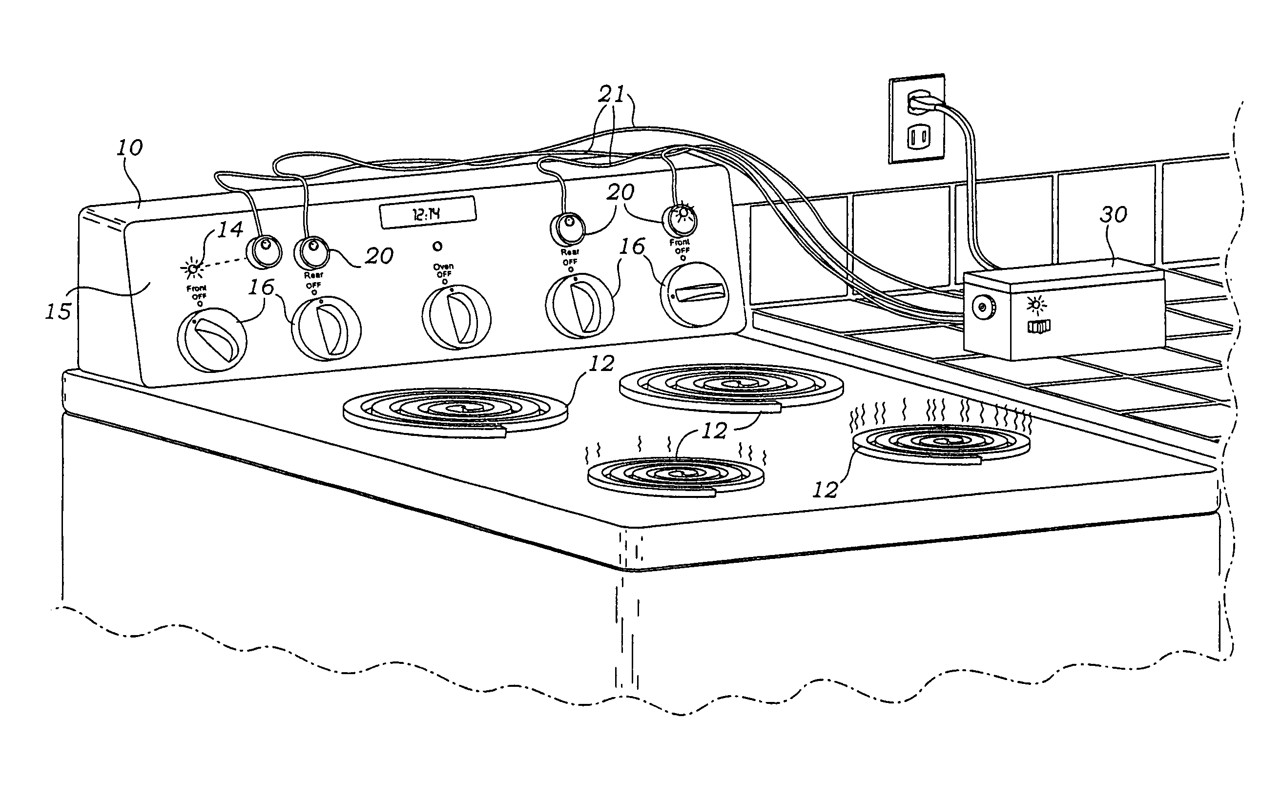
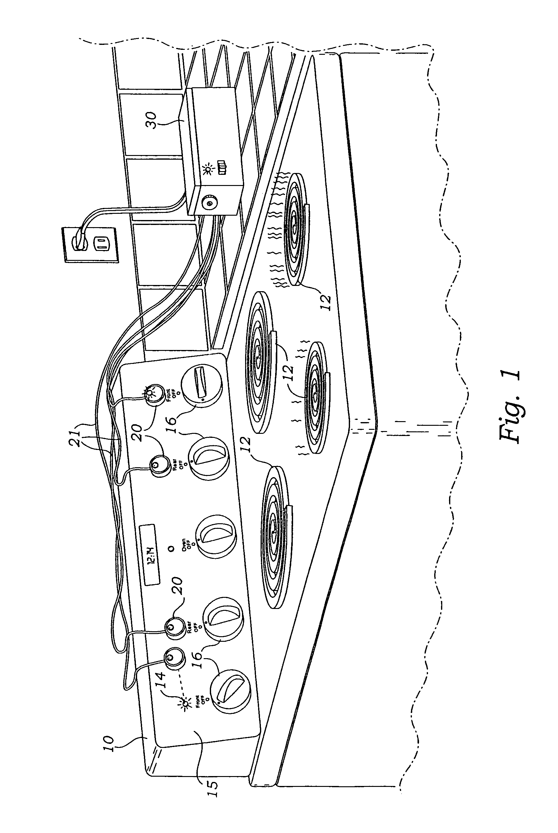
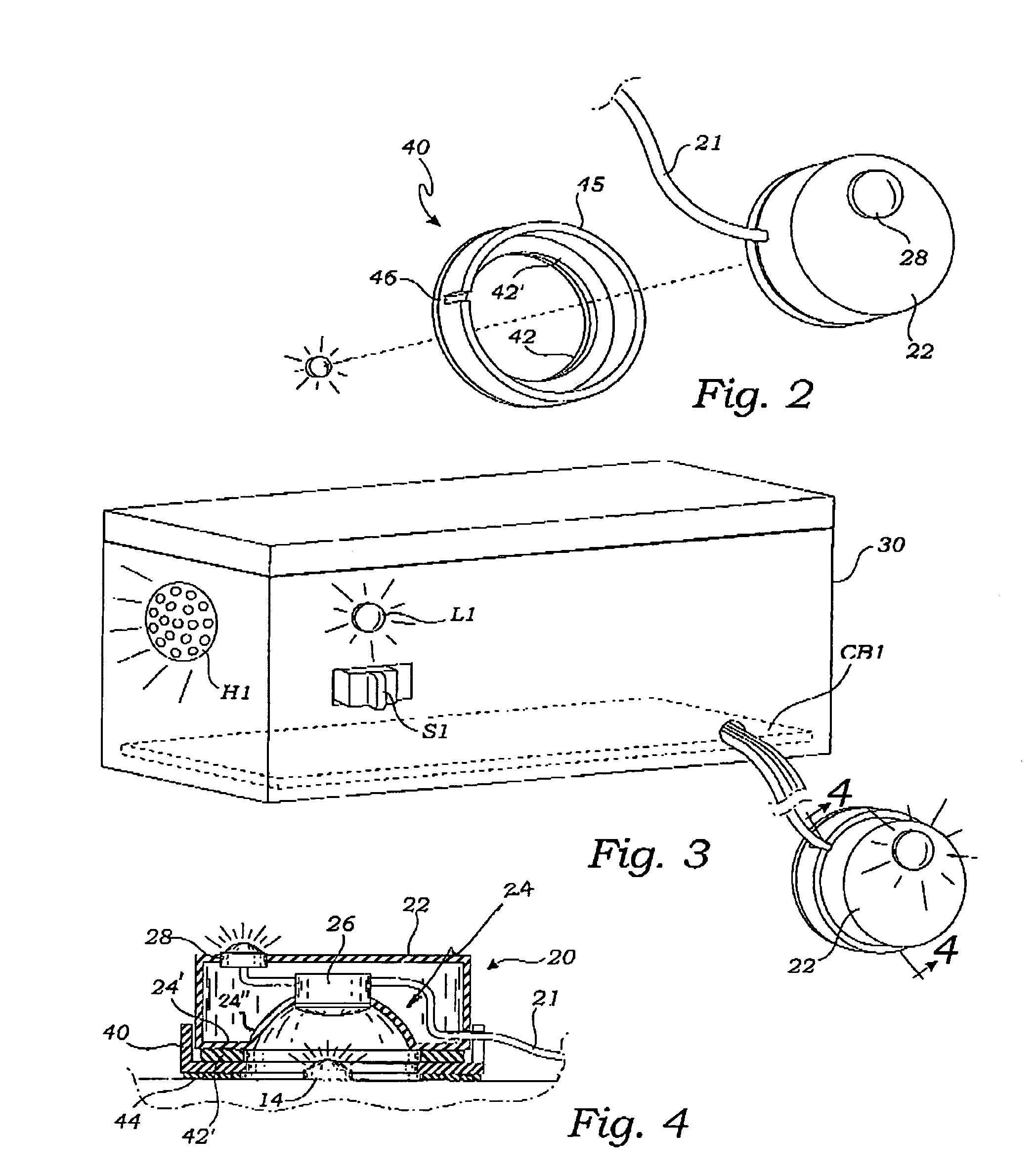
[0037]The present invention is an apparatus for providing safety and alert management to electrical appliances and particularly an electrical stove or range. As shown in FIG. 1, range 10 has cooking coils 12, typically 4 or 6 such coils 12, and range indicator lamps 14 to indicate when a coil 12 is in the “on” state. In many commercially available stoves, there may be fewer range indicator lamps 14 than cooking coils 12, so that a single range indic...


PUM


Abstract

A burner sensor is electrically interconnected with a control circuit, the burner sensor enabled for detection of burner operation, the control circuit providing a timing feature enabled, during burner operation, for continuous repetitive timing cycles each for a fixed selected time interval and for activating at least one of an audio, i.e., buzzer, and a visual alarms for a fixed duration, at the completion of each of the timing cycles. Thus the operator is alerted to the fact that a heating coil is hot so that a significant burn and fire hazard is avoided.

Description

INCORPORATION BY REFERENCE[0001]Applicant(s) hereby incorporate herein by reference, any and all U.S. patents and U.S. patent applications cited or referred to in this application.BACKGROUND OF THE INVENTION[0002]1. Field of the Invention:[0003]This invention relates generally to safety apparatus and in particular to such protective devices for commercial and residential electric ranges or stoves.[0004]2. Description of Related Art:[0005]The following art defines the present state of this field:[0006]Naugle, U.S. Pat. No. 4,255,669 describes a sensing apparatus for monitoring the operation of an electrical appliance. The sensing apparatus is plugged into a standard electrical outlet and the appliance to be monitored is plugged into the sensing apparatus. The appliance current flows through a transformer in the sensing apparatus. Detection circuitry including a comparator produces one signal when current flow through the transformer is negligible (appliance off) and another signal wh...

Claims


Application Information

Patent Timeline
Patent Type & Authority Patents(United States)
IPC IPC(8): H05B3/68G08B23/00
CPCH05B3/683
Inventor KLASK, RICHARD J.
Owner KLASK RICHARD J
Why Eureka
Try Eureka