
Method and apparatus for constructing a convex polygon that encloses a set of points in a region

Inactive Publication Date: 2006-02-21
CADENCE DESIGN SYST INC
View PDF9 Cites 20 Cited by
  • Summary
  • Abstract
  • Description
  • Claims
  • Application Information

AI Technical Summary

Problems solved by technology

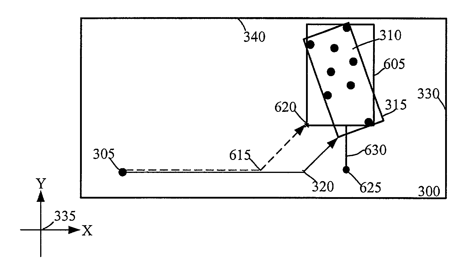
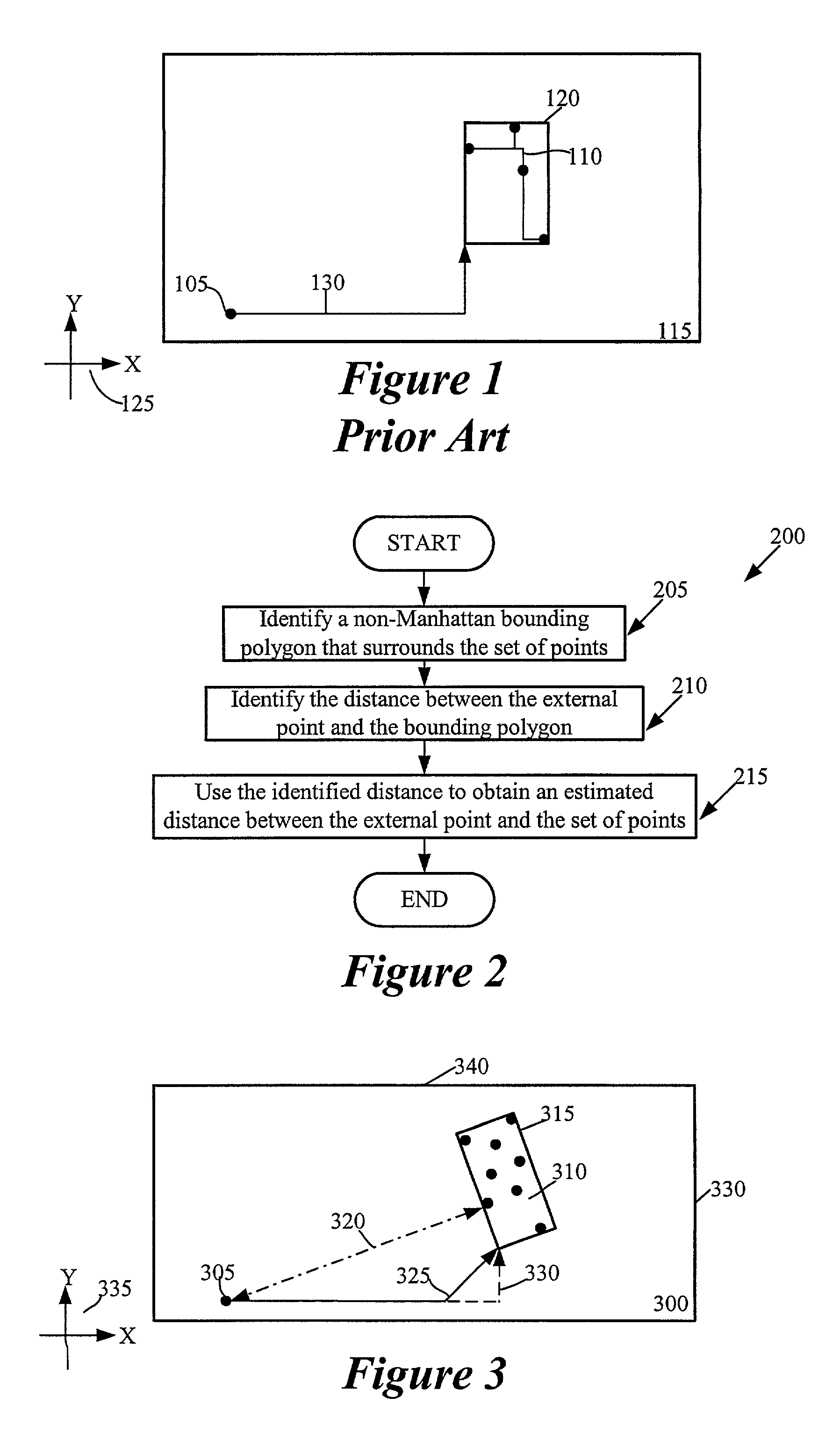
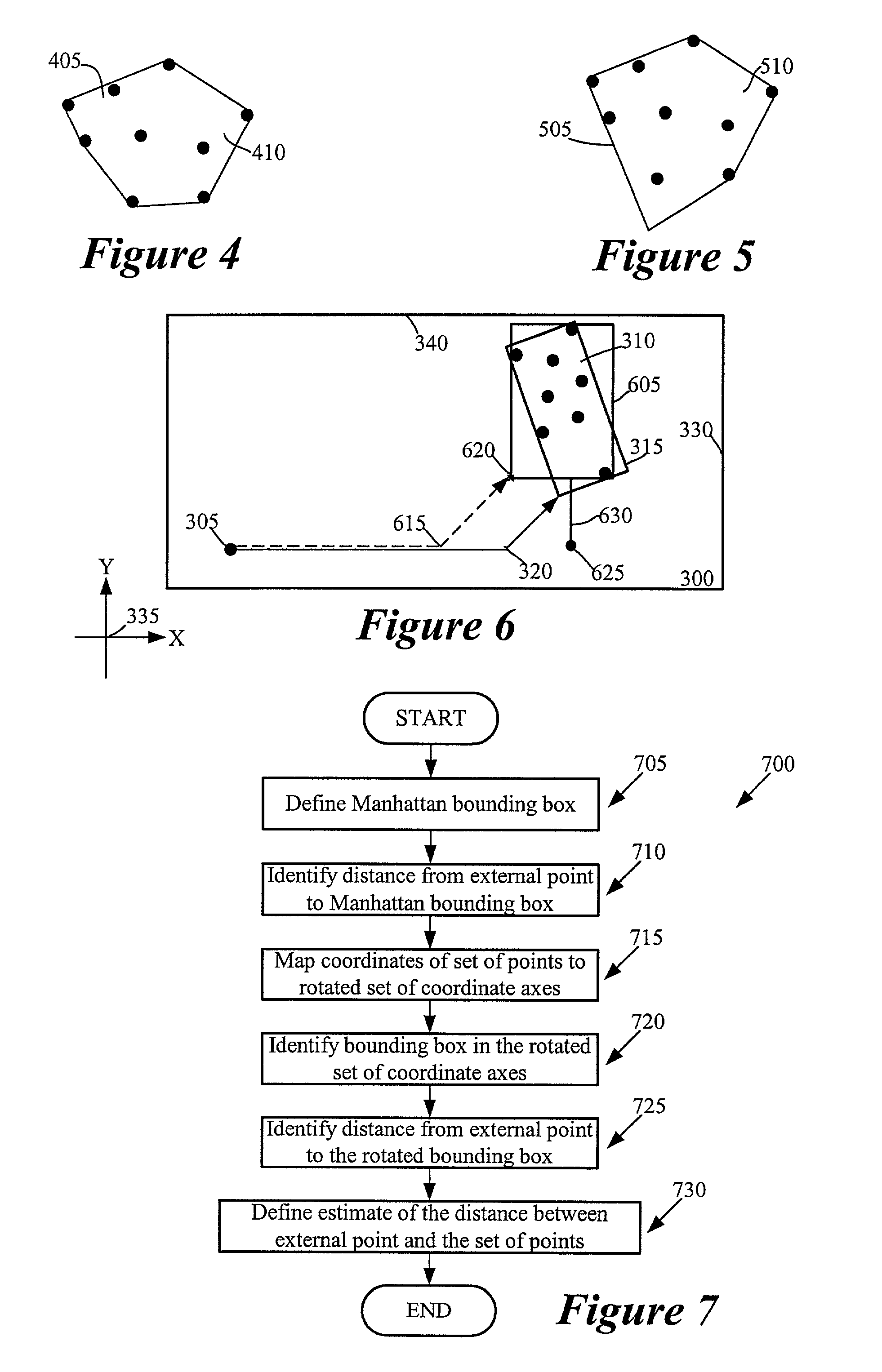
Also, the bounding box's position with respect to the external point 105 results in a poor estimated distance.

Method used


Image

  • Method and apparatus for constructing a convex polygon that encloses a set of points in a region
  • Method and apparatus for constructing a convex polygon that encloses a set of points in a region
  • Method and apparatus for constructing a convex polygon that encloses a set of points in a region

Examples


Embodiment Construction

[0031]In the following description, numerous details are set forth for purpose of explanation.

[0032]However, one of ordinary skill in the art will realize that the invention may be practiced without the use of these specific details. In other instances, well-known structures and devices are shown in block diagram form in order not to obscure the description of the invention with unnecessary detail.

[0033]Several processes are described below for computing estimated distances between a set of points and an external point outside of the set. In the embodiments described below, the points are within a region of a design layout. In other embodiments, however, the points can be in a region of any two or higher dimensional space. For instance, some embodiments can be employed for mapping, network routing, or any other application that uses computational geometry. In the design layout context, some embodiments can be employed in a variety of EDA or CAD tools, such as routers or placers.

I. N...


PUM


Abstract

Some embodiments of the invention provide a method for constructing a convex polygon that encloses a set of points in a region. This method identifies a first polygon that encloses the set of points. It then identifies a second polygon that encloses the set of points. The method then specifies the convex polygon as the intersection of the first and second polygons.

Description

FIELD OF THE INVENTION[0001]The invention is directed towards method and apparatus for constructing a convex polygon that encloses a set of points in a region.BACKGROUND OF THE INVENTION[0002]An integrated circuit (“IC”) is a device (e.g., a semiconductor device) that includes many electronic components, such as transistors, resistors, diodes, etc. These components are often interconnected to form multiple circuit components, such as gates, cells, memory units, arithmetic units, controllers, decoders, etc. An IC includes multiple layers of wiring that interconnect its electronic and circuit components. Traditionally, IC's use preferred direction (“PD”) wiring models, which specify a preferred wiring direction for each of their wiring layers. In preferred direction wiring models, the preferred direction typically alternates between successive wiring layers. One example of a PD wiring model is the PD Manhattan wiring model, which specifies alternating layers of preferred-direction hor...

Claims


Application Information

Patent Timeline
IPC IPC(8): G06T17/00
CPCG06T17/00G06T2210/12
Inventor TEIG, STEVENFRANKLE, JONATHAN
Owner CADENCE DESIGN SYST INC
Learn More