
Switching type power converter circuit and method for use therein

a power converter and switch type technology, applied in the direction of electric variable regulation, process and machine control, instruments, etc., can solve the problems of inability to achieve zero-voltage switching at light loads without additional circuit elements and additional complexity, and additional voltage stress on the primary switching elements required to reset the transformer cor

Inactive Publication Date: 2006-02-21
OLTRONICS
View PDF89 Cites 15 Cited by
  • Summary
  • Abstract
  • Description
  • Claims
  • Application Information

AI Technical Summary

Benefits of technology

This configuration reduces switch losses, enhances efficiency, and improves power density by maintaining zero-voltage and zero-current conditions during transitions, while simplifying circuit complexity and reducing the need for additional components.

Problems solved by technology

This technique has several drawbacks including the limited availability of phase-modulated integrated control circuits and the large number of parts, which include four primary switches, at least two secondary switches and at least two large magnetic circuit elements.
The technique suffers from an inability to accomplish zero-voltage switching at light loads without additional circuit elements and additional complexity.
Disadvantages of this converter include in additional voltage stress on the primary switching elements required to reset the transformer core.
However, these increased losses impose a limit on the level of power density and efficiency that can be obtained with this approach.

Method used


Image

  • Switching type power converter circuit and method for use therein
  • Switching type power converter circuit and method for use therein
  • Switching type power converter circuit and method for use therein

Examples


Embodiment Construction

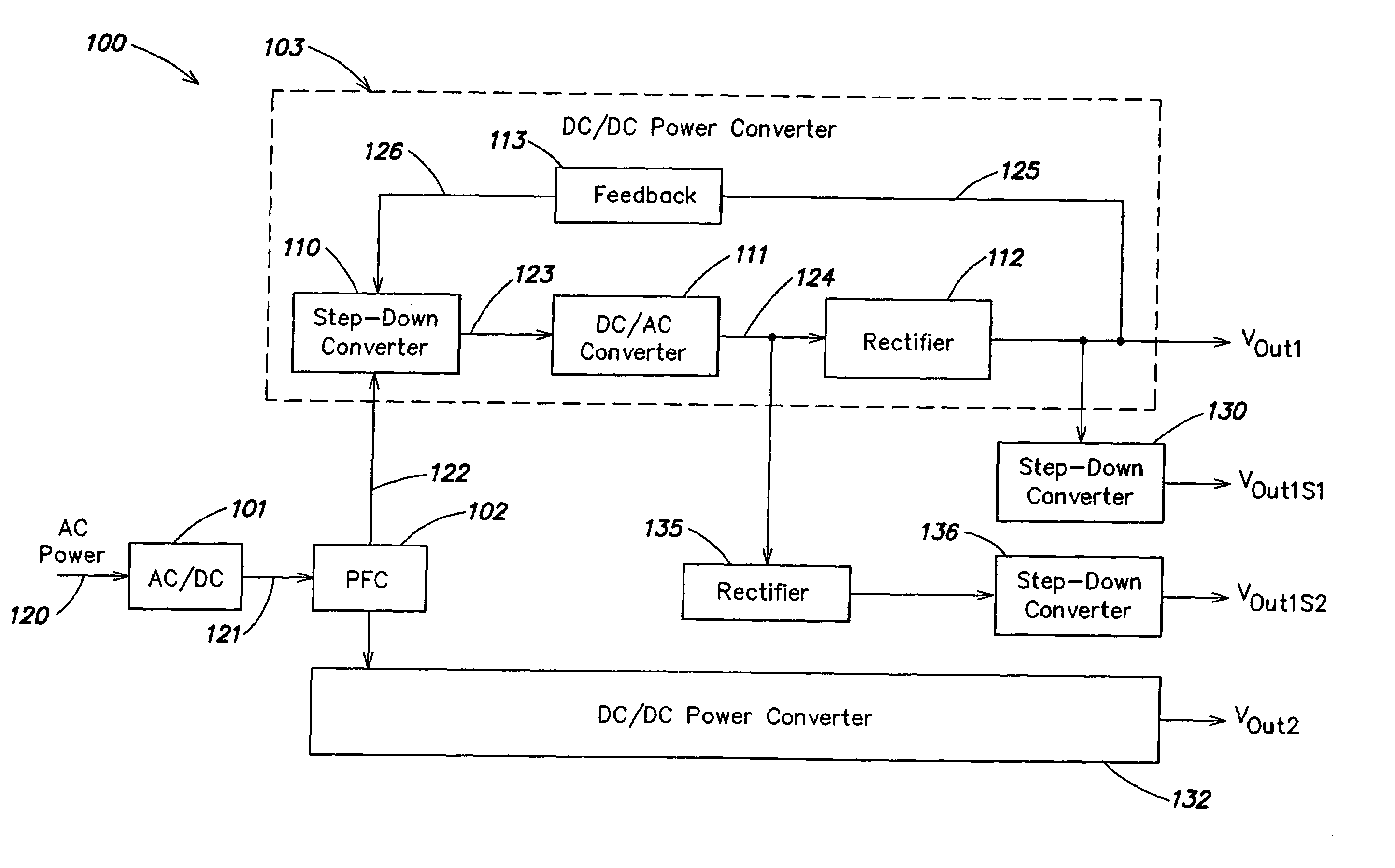
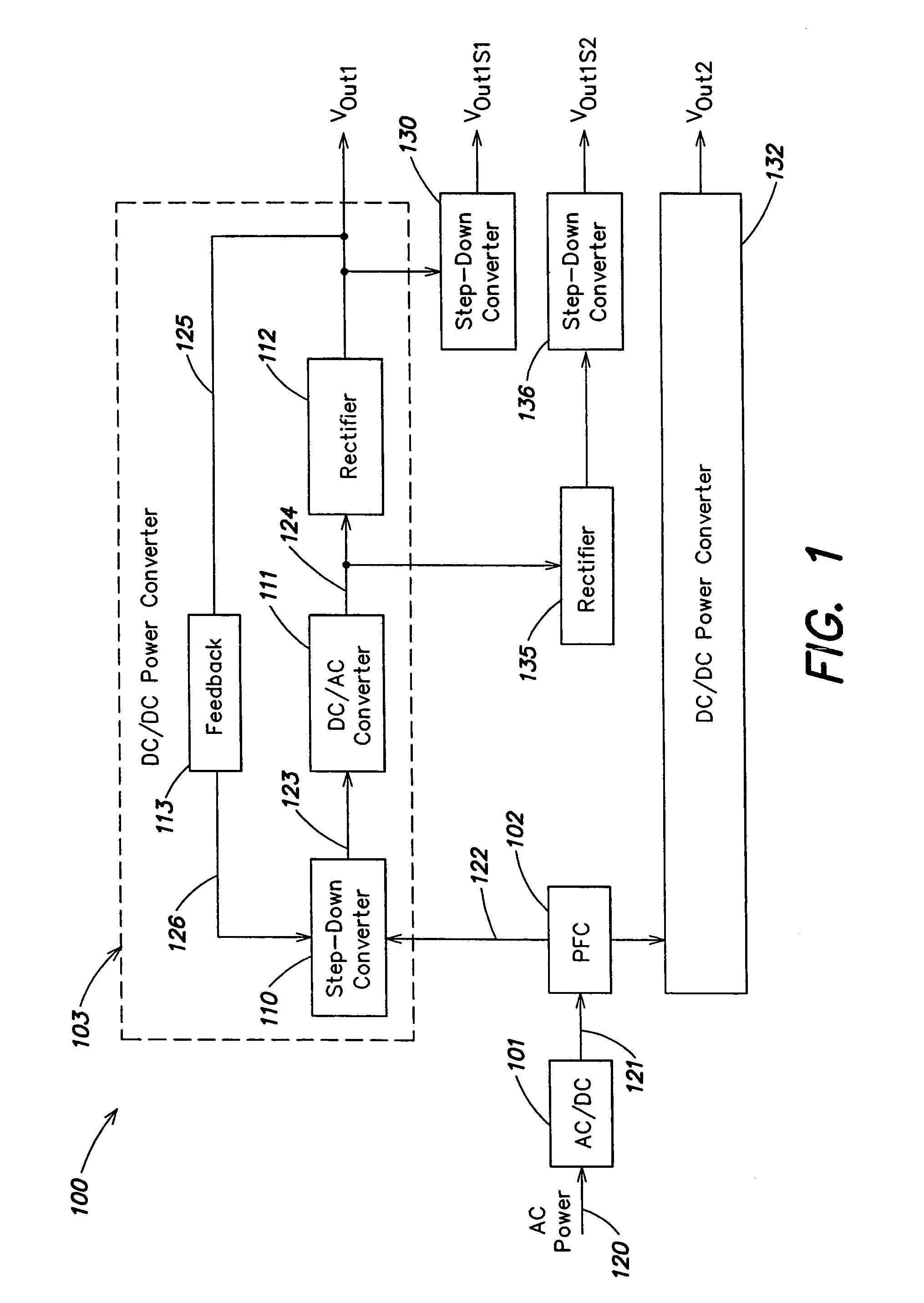
[0025]FIG. 1 shows an AC / DC power supply 100 that incorporates a DC / DC power converter circuit in accordance with one embodiment of the present invention. The DC / DC power converter circuit of the present invention may be used by itself, as a DC / DC power supply, or may be combined with one or more other circuits in forming other types of power supply circuits, for example as shown in FIG. 1 to provide an AC / DC power supply.

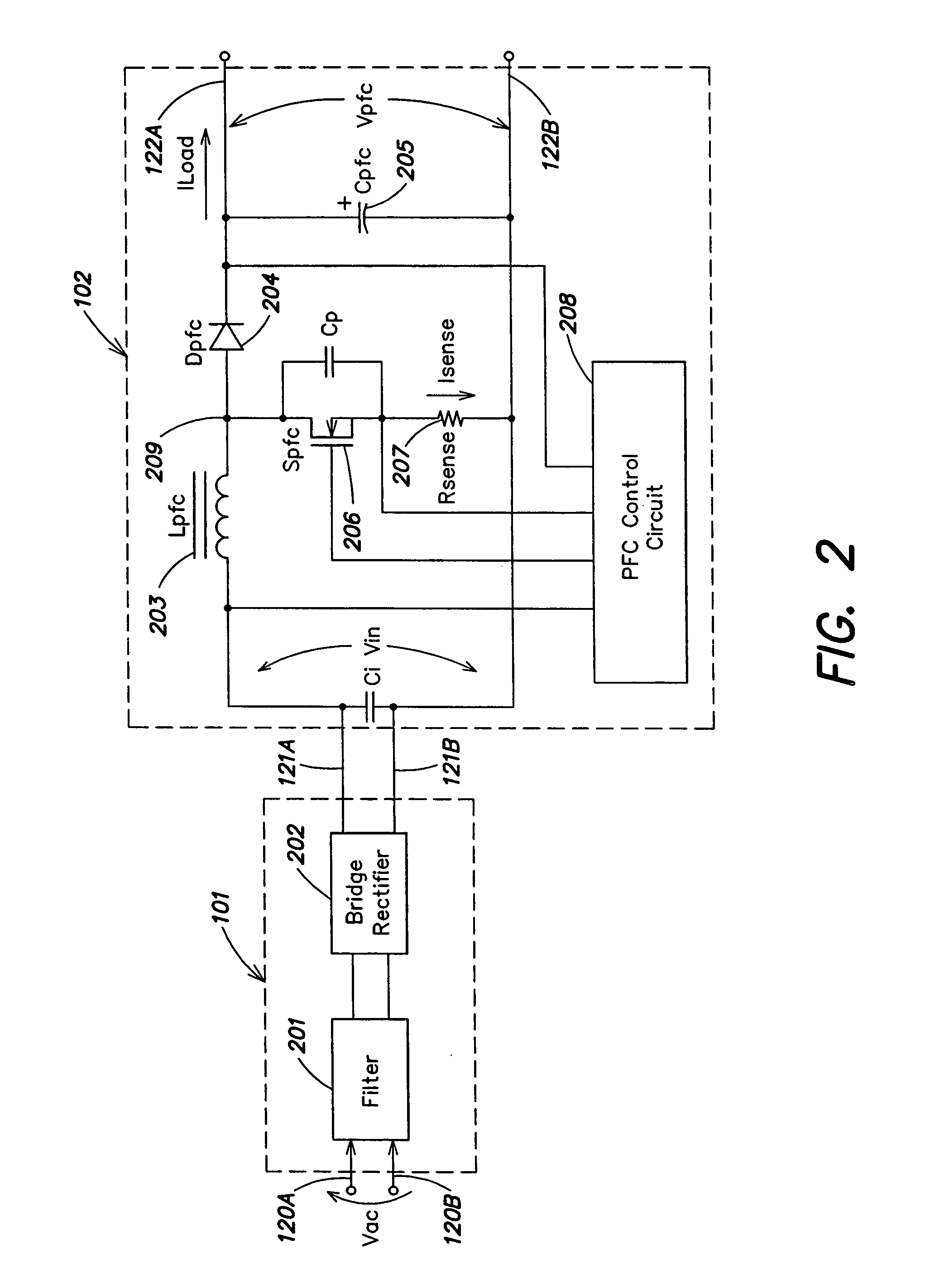
[0026]The AC / DC power supply 100 has three stages: an AC / DC converter stage 101, a power factor control (PFC) stage 102, and a DC / DC converter stage 103. The DC / DC converter stage 103 includes a step-down converter circuit 110, a DC / AC converter circuit 111, a rectifier circuit 112 and a feedback circuit 113. The step down converter circuit 110 and the DC / AC converter circuit 111 are each switching type power converter circuits. As stated above, switching type power converter circuits make use of switches, as well as capacitors, inductors and / or transformers, to co...


PUM


Abstract

A switching type power converter circuit includes a step-down converter circuit, a DC / AC converter circuit coupled to the step-down converter circuit, and a rectifier circuit coupled to the DC / AC converter circuit. In one embodiment, the DC / AC converter operates with near 50% duty cycle and with substantially zero-voltage, substantially minimum current switching in a resonant mode. An auxiliary step down converter may be added. An AC / DC converter front end with a full-wave bridge, an RF filter, and a power factor correction circuit may also be added.

Description

RELATED APPLICATIONS[0001]This application is a continuation of application Ser. No. 10 / 139,655, filed on May 2, 2002, now U.S. Pat. No. 6,807, 073, which claims the benefit of U.S. Provisional Patent Application Ser. No. 60 / 288,047, filed May 2, 2001. The entire contents of each application are hereby incorporated by reference.FIELD OF THE INVENTION[0002]The present invention relates to electronic power conversion circuits, and more specifically, to switching type power converter circuits.BACKGROUND OF THE INVENTION[0003]Many systems employ power converter circuits. These circuits receive electrical power in one form and convert it to another form, for example, to a form that is usable by electrical equipment employed within the particular system.[0004]One type of power converter circuit is referred to as a switching type power converter circuit or simply a switching power supply. Switching type power converter circuits make use of switches, as well as capacitors, inductors and / or ...

Claims


Application Information

Patent Timeline
Patent Type & Authority Patents(United States)
IPC IPC(8): H02J3/00H02M1/00H02M1/42H02M3/158H02M3/335H02M3/337
CPCH02M1/4225H02M3/158H02M3/33569H02M3/3376H02J2001/002H02J2001/008Y02B70/1491H02M2001/008Y02B70/126Y02B70/1425Y02B70/1433H02M2001/0058H02M2001/007Y02B70/10H02M1/008H02M1/0058H02M1/007H02M3/33573H02M3/33571H02M3/01H02J1/002H02J1/082
Inventor SCARLATESCU, GABRIEL
Owner OLTRONICS
Learn More